FFC LAF2501 Operator And Parts Manual Download Page 16


2/16/09

MR25607

14

BALE GRAPPLE MOUNTING

16. 

Insert the long legs of the two Hydraulic Bulkhead Run Tees (Item 5) down through the two  


holes in the plate on the inside of the Right Mounting Tube. Point the horizontal legs of the  


tees directly toward the other mounting tube so that those legs are parallel with the back of  


your bucket.  Rotate the horizontal legs 30° toward the bucket and secure the tees in that  


position by installing the two Hydraulic Jamb Nuts (Item 3) on the long legs underneath the  


mounting tube plate and tightening to 27 ft. lbs., + or - 2.0 ft. lbs.

17. 

Install the two 90° Female-Male Hydraulic Elbows (Item 2) on the long legs of the Hydraulic  


Bulkhead Run Tees, just below the jamb nuts.  The male legs of each elbow should be    


rotated so that exact alignment (i.e. 30° angle) is achieved with the horizontal leg of the tee  


above.  Tighten the elbow to 27 ft. lbs., + or - 2.0 ft. lbs.

18. 

Install the Hydraulic Orifice (Item 7) on the male leg of the rear 90° Female-Male Hydraulic  


Elbow.  Tighten the orifice to 27 ft. lbs., + or - 2.0 ft. lbs.

19. 

Install the two 1’-6” Hydraulic Hoses (Item 8): one between the top elbow on the right  


Hydraulic Cylinder and the vertical leg of the front Hydraulic Bulkhead Run Tee and the 


other between the bottom elbow on the right Hydraulic Cylinder and the vertical leg of the  


rear Hydraulic Bulkhead Run Tee. Tighten all four fittings to 27 ft. lbs., +/- 2.0 ft. lbs.

20. 

Install the 6-0” Hydraulic Hose (Item 1) between the top elbow on the left Hydraulic Cylinder  


and the horizontal leg of the front Hydraulic Bulkhead Run Tee. Tighten both fittings to 27 ft.  


lbs., + or - 2.0 ft. lbs.

21. 

Install the 5’-3” Hydraulic Hose (Item 9) between the bottom elbow on the left Hydraulic    


Cylinder and the horizontal leg of the rear Hydraulic Bulkhead Run Tee. Tighten both fittings  


to 27 ft. lbs., + or - 2.0 ft. lbs.

22. 

Install and snug up a Nylon Cable Tie (Item 30) around the two Left Hydraulic Cylinder    


hoses just below the lower Male-Male Hydraulic Elbow.

23. 

Install and snug up another Nylon Cable Tie around the two Right Hydraulic Cylinder hoses  


just above the lower Male-Male Hydraulic Elbow.   Note this will result in the rear hose being  


held twice in an inverted “J” shape by the tie.

24. 

The remaining Nylon Cable Tie will be installed as a part of the BALE GRAPPLE   


 HYDRAULIC 

CONNECTION.

25. 

Carefully raise the loader and cycle the tilt cylinders to check clearances and to verify that 


all mounting procedures have been successfully completed.  Make sure that no portion    


of this product makes any contact with your loader arms or dump cylinders.  If such a  


problem is encountered, stop the setup procedure immediately and contact  


FFC before proceeding further.

IMPORTANT 

Lubricate all grease fittings before connecting this product to your prime    

   mover’s 

hydraulic 

system.


Refer to BALE GRAPPLE MAINTENANCE and follow the instructions.

Summary of Contents for LAF2501

Page 1: ...lcg com 503 Gay Street Delhi IA 52223 United States of America SERIAL NUMBER ___________________ Manual Number MR25607 Part Number LAF2501 MODEL NUMBER ___________________ Rev 2 OPERATOR S AND PARTS M...

Page 2: ......

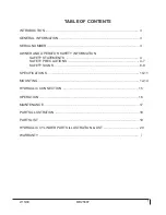
Page 3: ...ER 3 OWNER AND OPERATOR SAFETY INFORMATION SAFETY STATEMENTS 4 SAFETY PRECAUTIONS 4 7 SAFETY SIGNS 8 9 SPECIFICATIONS 10 11 MOUNTING 12 14 HYDRAULIC CONNECTION 15 OPERATION 16 MAINTENANCE 17 PARTS ILL...

Page 4: ...2 16 09 MR25607 2...

Page 5: ...hment Read this manual carefully to obtain valuable information and instructions that will help you achieve years of safe and dependable service The illustrations and data used in this manual were cur...

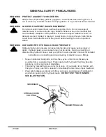
Page 6: ...ated to this equipment and the prime mover thoroughly before beginning installation operation or maintenance FOLLOW ALL SAFETY INSTRUCTIONS IN THIS MANUAL AND THE PRIME MOVER S MANUAL S READ AND UNDER...

Page 7: ...ITH HYDRAULIC FLUID PRESSURE Hydraulic fluid under pressure can penetrate the skin and cause serious injury or death Hydraulic leaks under pressure may not be visible Before connecting or disconnectin...

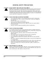
Page 8: ...specified by the tool manufacturer WARNING SAFELY OPERATE EQUIPMENT Do not operate equipment until you are completely trained by a qualified operator in how to use the controls know its capabilities d...

Page 9: ...ECAUTIONS CAUTION Obey all the safety instructions listed in this section and throughout this manual Failure to obey instructions in this section may result in personal injury Never leave the grapple...

Page 10: ...NS Keep all safety signs clean and legible Replace all missing illegible or damaged safety signs Replacement parts for parts with safety signs attached must also have safety signs attached Safety sign...

Page 11: ...2 16 09 MR25607 9 SAFETY SIGNS PART 40150 WARNING READ MANUAL PART 50 0724 WARNING HIGH PRESSURE FLUID PART 50 0737 WARNING PINCH POINT PART RDL3125 WARNING CRUSH HAZARD...

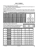
Page 12: ...to maintain full prime mover stability Note the shipping weight of your model then see the operator s manual s for your prime mover and loader and quick attach for ballasting needs ATTACHMENT SPECIFIC...

Page 13: ...2312 2743 3135 1 1 2 38 10 1649 1870 2236 2535 2686 3026 3642 4103 METRIC BOLT TORQUE SPECIFICATIONS NOTE The following torque values are for use with metric hard ware that is unplated and either dry...

Page 14: ...n the mounting process 3 Place your prime mover s transmission in Park and engage the parking brake 4 Lower the loader bucket completely so that the floor of the bucket rests fully on the level surfac...

Page 15: ...Locknut Be sure to steady the Cross Tube in place while installing the third bolt so that the Cross Tube does not slide out of position and fall Center the Cross Tube between the two Extension Tube i...

Page 16: ...lic Bulkhead Run Tee Tighten all four fittings to 27 ft lbs 2 0 ft lbs 20 Install the 6 0 Hydraulic Hose Item 1 between the top elbow on the left Hydraulic Cylinder and the horizontal leg of the front...

Page 17: ...y adapters and the male and female threads as well as the inside of the hoses and possibly fittings are clean Insert the male O ring ends of the hoses or fittings into the threaded valve body and tigh...

Page 18: ...anties If the grapple is ever used as a rake to drag materials into a position for being picked up the grapple must be completely open Applying a raking type force to the partially open grapple will g...

Page 19: ...ard to read BEFORE EACH USE Make sure that all nuts and bolts are in place and properly tightened Make sure that all other fasteners are in place and are performing their specified function Make sure...

Page 20: ...84 6 ft lbs Torque to 84 6 ft lbs Torque to 84 6 ft lbs Torque to 84 6 ft lbs Torque to 84 6 ft lbs Torque to 84 6 ft lbs Torque to 84 6 ft lbs Torque to 84 6 ft lbs Torque to 300 10 ft lbs Torque to...

Page 21: ...F9811 Pin 1 x 5 25 Greasable 15 6 LAF9866 Cross Tube Mounting Plate 16 4 LAF9867 Grapple Tooth 17 2 LAF9873 Extension Tube 18 1 LAF9874 Cross Tube 19 2 LAF9978 Pin 1 x 4 75 Greasable 20 2 LAF9979 Pin...

Page 22: ...Tube End and Ports Parallel to Cross Tube 2 1 LAF4620 Shaft 1 25 Dia with Cross Tube End 3 1 LAF4619 Head 2 OD x 1 25 ID Nominal 4 1 LAF4618 Piston 2 OD x 75 ID Nominal 5 1 LAF4129 Nut 75 Dia 16 tpi G...

Page 23: ...tion to repair or replace the product b Timely Repair and Notice In order to obtain the Limited Warranty i the product must be repaired within thirty 30 days from the date of failure and ii a claim un...

Page 24: ......

Reviews: