background image

Electrical Connection 

1.  Verify that the actual voltage at the electrical service connection is compatible with the specifications on the 

brewer’s serial number label.  Make sure the electrical service includes 

neutral

2.  The temperature and water tank fill level are pre-set at the factory.  There is no need to turn off the heaters 

during the installation process.  The heaters are disabled by the control board until the tank is full of water.  
The heating process will start automatically when the tank has filled. 

3.  Only 120vac powered units are shipped from the factory with power cords and plugs attached.  For other 

voltages, a terminal block is provided for connecting the incoming power wires.  Consult local codes to 
determine if a cord and plug can be installed, or if the unit must be hard wired. 

4.  A fused disconnect switch or circuit breaker on the incoming power line must be conveniently located near 

the brewer, and its location and markings known to the operators. 

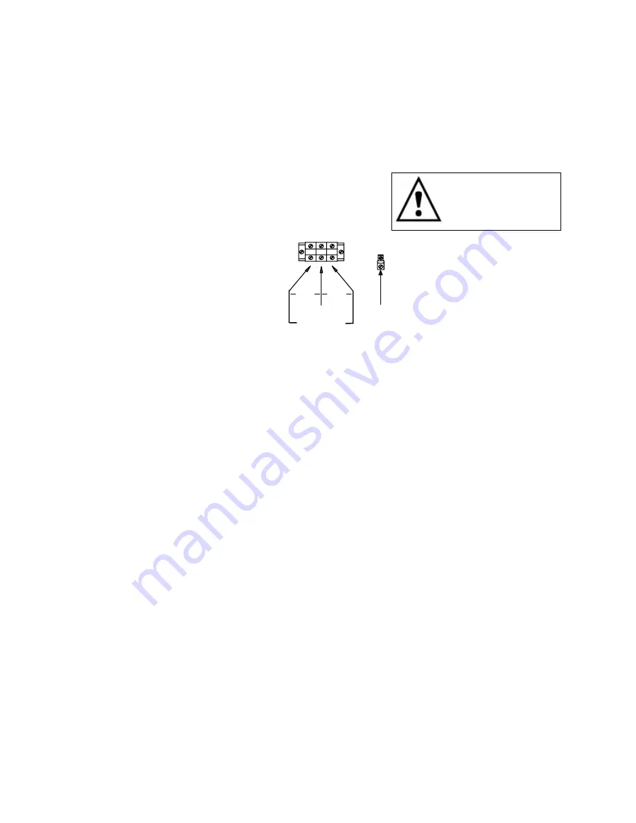
5.  The body of the brewer must be grounded to a suitable building 

ground.  A ground lug is provided in the brewer next to the power 
terminal block.  Use only 10 gauge copper wire for grounding. 

6.  Electrical connections must be secured in-place within the unit to 

meet national and local standards. 
 

L1

L2

N

GROUND LUG

GROUND

WIRE

SINGLE PHASE

TERMINAL BLOCK

N

208-240V

120V

120V


Electrical Configuration – US & Canada 


7.  Finally, connect the incoming power wires to the terminal block in accordance with applicable codes. 


Final Setup 

1.  Turn on the incoming water supply line and inspect both inside and outside of the brewer for leaks in all 

fittings and tubes 

2.  Turn on the incoming power. 
3.  Turn on the brewer’s main power switch. 
4.  Within 6 seconds, the hot water tank will begin filling until the water is sensed by the probe at the top of the 

tank. 

5.  The heaters will be disabled by the control board until the tank is full. 
6.  The brewer will be ready for operation as soon as the ready light comes on to signify that the water tank is 

up to temperature. The time required to reach brewing temperature will vary according to the electrical 
configuration ordered. 

7.  Review the Operating Instructions. Brew one full batch (water only) on each side to confirm proper fill 

levels. The brewer is factory set with water only (no coffee) to dispense the correct amount of water. With 
water only, the correct level can be observed as being approximately ¼ inch below the top edge of the 
container. 

8.  Re-attach the covers after one final inspection for leaks.  Look closely in the top of the brewer at the 

dispense fittings during this inspection. 


Operator Training 

Review the operating procedures with whoever will be using the brewer.  Pay particular attention to the following 
areas: 
 
1.  Don't remove the brew basket until it has stopped dripping.  
2.  Make sure the dispenser is empty before brewing into it. 
3.  Show how to attach covers, close, and or secure the dispensers for transporting. 
4.  Show the location and operation of the water shut off valve as well as the circuit breaker for the brewer. 
5.  Steam from the tank will form condensation in the vent tubes.  This condensation will drip into and then out of 

the brew baskets.  1/4 cup discharging overnight is possible.  Place an appropriate container under each brew 
basket when not in use. 

6.  We recommend leaving the power to the brewer on overnight. The water tank is well insulated and will use very 

little electricity to keep the tank hot.  Leaving the brewer in the on position will also avoid delays at the 
beginning of shifts for the brewer to reach operating temperature. 


Warning: To prevent 

                 electrical shock, this 
                 unit must be properly 
                 grounded.


Summary of Contents for CBS-11H

Page 1: ...S 1000 Series Coffee Brewers Table of Contents Contact Information 2 Product Description Features 2 Technical Data 2 Brewing Specifications 2 Weights and Capacities 2 Electrical Configuration and Brew...

Page 2: ...lite servers and Total serviceability from the front warming stands Guard protected gauges and faucets Hot water service Self locking container bottoms Can be added at any time Technical Data Brewing...

Page 3: ...5 0 11 0 C11041 1 X 4000 watt 120 208 1 ph 3 ground 3 2 15 7 5 0 11 0 120 220 1 ph 3 ground 3 7 17 1 5 8 11 0 120 240 1 ph 3 ground 4 2 18 0 6 6 11 0 CBS 12H 1 5 gallons per batch Electrical Heater V...

Page 4: ...4 Dimensions Utility Connections CBS 11H CBS 12H...

Page 5: ...installing Verify that the brewer will fit in the space intended for it and that the counter or table will support the total weight of the brewer and dispensers when filled 2 The brewer s legs are shi...

Page 6: ...t water tank will begin filling until the water is sensed by the probe at the top of the tank 5 The heaters will be disabled by the control board until the tank is full 6 The brewer will be ready for...

Page 7: ...he sight gauge tube CAUTION both the coffee or water may still be hot enough to cause burns so be careful when draining the dispensers 4 Place the dispenser s in position under the brew baskets Ensure...

Page 8: ...ispensed and the water level drops below the probe a fill signal is sent to the fill valve If no water is sensed by the probe after 40 seconds the voltage to the thermostat and the heaters is removed...

Page 9: ...disc above the spray cutter The standard hole in the flow disc is 240 Other flow discs are available for special situations like high levels of by pass The sprayhead can be assembled incorrectly duri...

Page 10: ...ve the dispense tube 1 Unscrew seal locknut and release the drive screw from dispense tube shaft 2 Turn the dispense tube slightly back and forth while pushing the tube into the hot water tank until i...

Page 11: ...to lower the tank temperature Wait for the ready light to come on and measure the temperature again Repeat until the desired temperature is obtained Effective April 1 2004 A new digital thermostat an...

Page 12: ...setting of the dial before making any adjustments Turn the knob clockwise to increase and counter clockwise to decrease the timer setting On the dual portion timer the knob labeled T1 controls the fu...

Page 13: ...ct with the coffee grounds The bypass can be adjusted from 0 to 33 of the total brewing water Dual brewers CBS 12H have separate bypass valves on each side Unless requested at the time of order all br...

Page 14: ...ont 2 11 12 71036 Faucet C ring for retaining faucet union nut 3 11 12 102019 Faucet Shank assy 1 5 gal container 4 11 12 13015 Faucet Shank Locknut 1 5 gal container 5 11 12 71025 Sight glass vented...

Page 15: ...04 Brew handle Screw 6 32 x 5 8 ss r h 44 11 12 82018 Brew handle Screw 8 32 x 2 ss r h 44 11 12 13005 Brew handle Safety Handle 44 11 12 102010 Brew handle start stop assy 44 11 12 002036 Brew handle...

Page 16: ...2 52001 Terminal block mounting track 76 11 12 102040 Terminal block assy 2 pole export 120v 11 51 s 76 11 12 102041 Terminal block assy 3 pole 76 11 12 52002 Terminal block only requires mouting trac...

Page 17: ...Brew Basket Wire insert 13x5 ice tea 1 2 batch 87 11 12 101063 Warmer assy upper cover optional 2 x 100w 120v 88 11 12 101080 Warmer assy Up 2x100w 220vac export 88 11 12 53032 Warming plate assy 100w...

Page 18: ...rate is too low or fluctuates too much to support a full brew problem is worse in simultaneous brews Make sure brewer has a dedicated water line Ensure that the shut off valve is open all the way Nev...

Page 19: ...e to see if it leaks water to the tank Coffee tastes too strong Incorrect dosage Measure and confirm the correct amount of coffee required Short brew levels See Short brew levels above Temperature Pro...

Page 20: ......

Reviews: