Basic valve
VZWE-...-M22C-M-...-...-H
Festo AG & Co. KG
Postfach
73726 Esslingen
Deutschland
+49 711 347-0
www.festo.com
Operating instructions
8025408
1303NH
[8025409]
Original: de
Basic valve VZWE-...-M22C-M-…-...-H
English
. . . . . . . . . . . . . . . . . . . . . . . . . . . . .
1
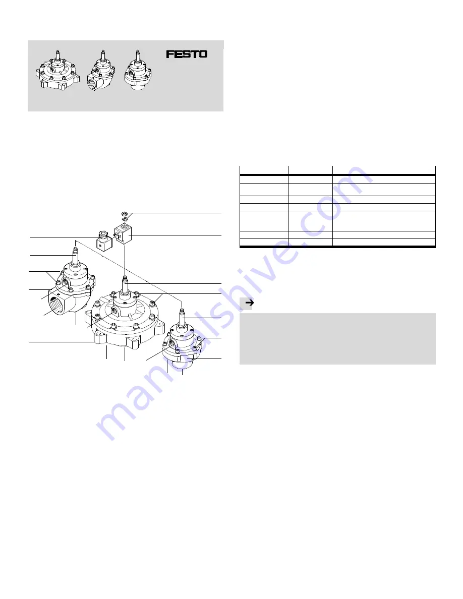
Design
1
a
b
a
b
a
b
c
c
c
2
3
4
1
5
2
1
6
3
2
3
1
Valve body (basic valve)
1)
a: Connection 1: input (IN)
2)
b: Connection 2: output
2)
c: From nominal diameter 40 mm:
air vent
2
Cover screw — number and design
dependent on type
3
Armature guiding tube
4
Optional: socket with seal and
mounting screw (accessories)
1)
5
Hex nut and disc-spring washer for
attachment
6
Optional: solenoid coil with
connection in accordance with
EN 175301-803, form A
(accessories)
1)
1)
Design type-dependent
2)
For straight design (VZWE-F..): input external; output internal;
Fig. 1
2
Function
The VZWE pulse valve is a piloted 2/2-way valve. For operation, the basic valve
must be equipped with an appropriate solenoid coil (
Fig. 1,
6
). Appropriate
are solenoid coils in accordance with the accessories (
section 10).
The valve requires differential pressure between input and output to function cor-
rectly (
section 13). Starting with a nominal diameter of 40 mm, the valve has an
opening for fast external exhaust (
Fig. 1,
1
c ).
This permits high switching speeds despite corresponding sizes. For smaller nom-
inal diameters, exhaust takes place internally through the output.
The valve’s drive fulfils a pilot function. When current flows, the excited magnet
pulls the armature against the force action of a spring. The differential pressure
lifts the main sealing element (diaphragm). The valve opens.
The valve is closed in the de-energised status (normally closed - NC). Supply pres-
sure and spring act on the diaphragm and so seal the valve.
3
Application
Pulse valves of the series VZWE are intended for generating compressed air im-
pulses for mechanical cleaning of filters in dust filter systems. Typically, the valve is
triggered with short electrical impulses. As a result, at the output of the valve,
short compressed air pulses are generated through the filter opposite to the nor-
mal direction of flow of the filter system to release adhering dust particles from the
filter. Only little resistance may operate at the valve output. Therefore, pipelines
with equal or larger nominal diameter are required at the output.
• Take into consideration the legal regulations applicable for the destination as
well as:
– regulations and standards
– regulations of the testing organizations and insurers
– national regulations.
• The product may only be used in its original status without unauthorised modi-
fications. Only the assembly and commissioning activities described in these
operating instructions are permissible. Dismounting the armature guiding tube
is impermissible.
• Only use the product if it is in excellent technical condition.
• Comply with the permissible limit values and specifications (
Technical data).
• Make sure the compressed air is properly prepared (
Technical data).
• Only use the valve in the flow direction indicated (
Fig. 1,
1
a and
1
b).
4
Product variants
Features
Type codes
Description
Type
VZWE–
Solenoid-actuated pulse valve
Type of directional
control valve
E–
F–
Angle valve (angle design)
Flanged valve (straight design)
Valve function
M22C–
2/2-way valve, normally closed (NC)
Reset method
M–
Mechanical spring
Process valve
connection
G34–, G1–, G112–,
G2–, G212–,
Pipe thread in accordance with DIN ISO 228
F600–, F750–, F890–
Flange diameter 60 mm, 75 mm, 89 mm
Nominal size
200 ... 760
20 mm to 76 mm
Electrical connection
–H
With 14 mm armature tube
Fig. 2
5
Transport and storage
• Ensure the following storage conditions: short storage times in cool, dry, shaded
and corrosion-resistant locations.
6
Installation
Note
• Installation should only be conducted by qualified personnel.
• Electrical connections should only be established by electricians.
• Avoid contamination. In this way you will prevent small holes from becoming
blocked and restriction or blockage of the function.
• Avoid mechanical stresses, particularly on the solenoid coil and the armature
guiding tube.
• Ensure adequate heat circulation at the place of installation.
6.1 Mounting of the solenoid coil – in accordance with accessories
(
section 10)
1. Push the solenoid coil over the armature guiding tube.
2. Fasten the solenoid coil with disc-spring washer and hex nut (
Fig. 1) – tight-
ening torque: 2 Nm.
6.2 Installation of the valve
You can find information about the geometric data of the product in our catalogue
(
www.festo.com/catalogue).
1. Check the system requirements before installation:
– The piping system is unpressurised and no medium flows in it.
– Pipeline and connecting thread or connection flange are clean.
– The pipeline ends are mounted.
– The power supply is switched off.
2. Put the valve in its mounting position. Observe the flow direction. The flow direc-
tion is permissible only from the input to the output. Input and output
Fig. 1
1
a and
1
b. For some designs, the input is marked with IN.
3. Screw the valve plugs into the pipeline ends. Observe the permissible tightening
torques (
Technical data).
4. Establish the electrical connection. Use only an appropriate socket for this pur-
pose (form A,
Fig. 1,
4
).
5. Connect the power supply. The required current type and voltage is dependent
on the type of solenoid coil (
section 10 and name plate on the product).


