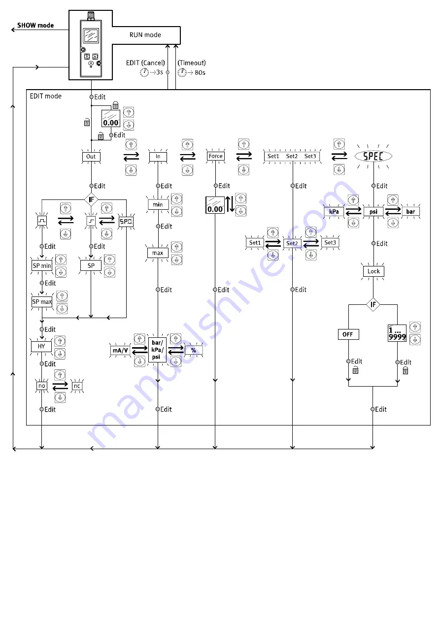
1) Depends on the version of the VPPM−...C1
2) Depends on the setting in the [SPEC] menu
1)
2)
Not in function (FORCE)
Fig.21 EDIT mode
Page 1: ...egulating a pressure proportional to a specified setpoint value A built in pressure sensor records the pressure at the working line and compares this value with the setpoint value If the actual value differs from the setpoint value the regulating valve is actuated further until the output pressure reaches the setpoint value W W 3 1 2 X Supply port Setpoint value Setpoint value Pressure output Exha...
Page 2: ...s Fig 8 Wall mounting in line valve Fasten the VPPM C1 in the intended position with two M4 screws In order to do this use angle bracket type VAME P1 A see diagram When mounting the VPPM with the aid of the bracket the VPPM C1 may only be loaded statically torque 1 0 Nm Fig 9 H rail mounting in line valve Mount the H rail adaptor on the VPPM C1 using the screws included x M4 x 65 M4 x 77 tightenin...
Page 3: ...t a switching point manually as follows 1 In order to activate the EDIT mode press the EDIT button Out flashes 2 Press the EDIT button twice SP flashes 3 Edit the threshold value shown with the UP or DOWN button 4 Hold the EDIT button pressed down for 3 s The VPPM C1 will then be in the RUN mode 6 2 Preparing for commissioning Note Make sure that the VPPM C1 is not subjected to high frequency irra...
Page 4: ...Fig 20 If the VPPM C1 is in RUN mode the SHOW mode will become active when the UP button or the DOWN button is pressed twice If the output Out is selected the current settings of the switching output Out will be displayed one after the other each time the UP button is pressed If the input In is selected the minimum pressure value and the maximum pres sure of the input In will be displayed one afte...
Page 5: ...1 Depends on the version of the VPPM C1 2 Depends on the setting in the SPEC menu 1 2 Not in function FORCE Fig 21 EDIT mode ...
Page 6: ...min SP max Fig 24 Switching points SP and hysteresis Hy with NC setting normally closed contact With threshold value comparator setting P 1 0 SP Hy OUT Withwindow comparator setting P 1 0 OUT SP min SP max Hy Hy Fig 25 Configuring the switching output 1 In order to activate the EDIT mode press the EDIT button Only with active security locking Lock flashes 2 Press the UP DOWN button until the desir...
Page 7: ... 1 2 bar type 0 02 bar 2 bar 6 bar type 0 06 bar 6 bar 10 bar type 0 1 bar 10 bar 1 FS Full scale 1 FS 0 1 V or 4 16 mA 100 FS 10 V or 20 mA Output pressure 0 V or 4 mA creates an output pressure of 0 bar Fig 30 Select a suitable parameter set Recommended parameter sets VPPM Sizes 1 8 Tube length 1 Open sys Output values in ml g p y tem 0 100 100 1000 1000 0 m 3 3 2 1 1 m 3 3 2 2 3 m 3 3 3 2 5 m 3...
Page 8: ...socket according to Accessories Perm temp range Ambient Medium Storage C 0 50 10 50 10 70 Vibration and shock Vibration Shock The following data does not apply to mounting the VPPM to the angle bracket VAME P1 A Tested according to DIN IEC 68 EN 60068 part 2 6 for wall mounting 0 35 mm path at 10 60 Hz 5 g acceleration at 60 150 Hz Tested according to DIN IEC 68 EN 60068 part 2 27 for wall mountin...