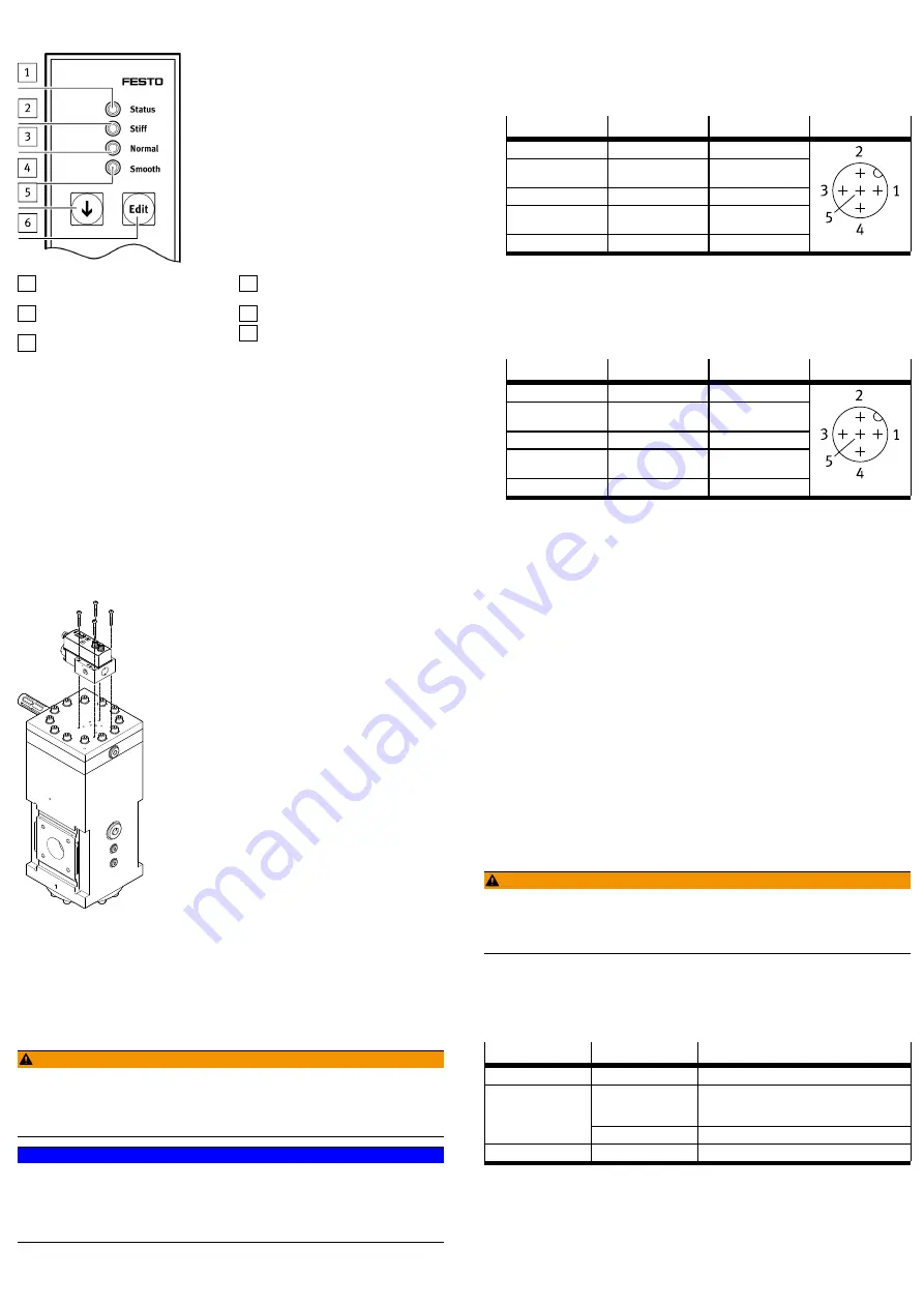
5.2.1
Display and operating components
1 LED status (red/green) status
indicator
2 LED stiff (blue) fast control reac-
tion
3 LED normal (blue) normal control
reaction
4 LED smooth (blue) precise control
reaction
5 DOWN pushbutton
6 EDIT pushbutton
Fig. 3 Display and operating components
6
Assembly
6.1
Mounting
Requirements:
–
The piping is unpressurised and there is no medium flowing through it.
–
The supply lines are clean and free of wear-causing particles.
–
Shut-off valves for exhausting the system are installed in the compressed air
supply line.
–
When combining the VPPL with the PREL, both products must have the same
valve variant in the type code.
–
VPPL-…-1 with PREL-…-1
–
VPPL-…-2 with PREL-…-2
–
VPPL-…-x with PREL-…-x
Fig. 4 VPPL and PREL
•
Flange-mount the VPPL on the PREL.
–
Provide a mounting clearance for cable connection and tubing connec-
tions.
–
Tightening torque for retaining screws: 3.8 Nm ± 10%
7
Installation
7.1
Electrical installation
WARNING!
Risk of injury due to electric shock.
•
For the electrical power supply with extra-low voltages, use only PELV circuits
that guarantee a reliable separation from the mains network.
•
Observe IEC 60204-1/EN 60204-1.
NOTICE!
The service interface is for diagnostics only. If this push-in connector is used to
operate the valve, the control electronics may be damaged.
•
Never connect the service interface to a component that provides a power
supply.
•
Always keep the service interface closed with a cover cap.
1. Before establishing the electrical connection, check the connecting cable:
–
Use pre-assembled cables from Festo.
–
Max. length of the signal lines is 30 m.
–
The cables are not crushed, kinked or stretched during installation.
2. Screw the signal cable to the "Output actual value" connection.
–
Tightening torque 0.5 Nm ± 20%
Pin
Cable colour
1)
Allocation
M12 plug
1
–
not assigned
2
white (WH)
Analogue Out+(actual
value)
3
–
not assigned
4
black (BK)
Analogue Out– (actu-
al value)
5
grey (GY)
FE
1) When using the pre-assembled Festo cables
Tab. 3 Pin allocation for "Output actual value" connection
3. Earth the shielding at the end of the cable away from the product.
4. Screw the connecting cable to the "input setpoint value/power supply" con-
nection.
–
Tightening torque 0.5 Nm ± 20%
Pin
Cable colour
1)
Allocation
M12 plug
1
brown (BN)
24 VD C
2
white (WH)
Analogue In+ (set-
point value)
3
blue (BU)
0 V
4
black (BK)
Analogue In– (set-
point value)
5
grey (GY)
FE
1) When using the pre-assembled Festo cables
Tab. 4 Pin allocation for "Input setpoint value/power supply" connection
8
Commissioning
8.1
Initial start-up
Requirements:
–
For VPPL-3L (sleeve version):
–
The VPPL is completely connected and ready for operation.
–
For VPPL-3Q (flange version):
–
The VPPL is flange-mounted to the PREL.
–
The PREL is completely connected and ready for operation.
1. Switch on the supply voltage.
2. Switch on operating pressure.
3. Switch on the voltage for the setpoint signal.
4. Start the VPPL and PREL together.
5. Select parameter set for the closed-loop controller.
–
Press and hold the EDIT pushbutton for 3 seconds.
The LED for the current controller setting flashes blue (factory setting:
normal control behaviour).
–
Select the desired parameter set with the DOWN pushbutton.
The LED of the required parameter set flashes blue.
–
Press EDIT pushbutton.
The selection is accepted, and the LED is steady blue.
8.2
Re-commissioning
WARNING!
Risk of injury from compressed air/pressure surge.
Products under pressure can cause personal injury.
•
Before applying the supply pressure set the setpoint value of the VPPL to
zero.
1. Set setpoint value to zero.
2. Apply supply pressure.
3. Set required setpoint value.
9
Operation
Status LED
Display
Description
green
Steady light
Electronic control OK
Flashing light
Undervoltage or overvoltage.
The valve is no longer operational in this status.
The error is cancelled by a correct power supply.
red
Steady light
Malfunction, valve failure
off
off
Valve not ready for operation
Tab. 5
10
Maintenance
Prior to all maintenance work
1. Switch off analogue setpoint signal.
2. Switch off the operating voltage and secure it against being switched on
again.


