

12.2
Device variants with LCD display
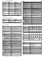
Fault description
Cause
Remedy
[Er01] / [FAIL]
1)
Device error
Replace device.
[Er02] / [ASIC]
1)
Device error
Replace device.
[Er10] / [OVER]
2)
Measuring range exceeded
Comply with the measuring
range.
[Er17] / [SUPL]
2)
Undervoltage
Apply permissible operating
voltage.
[Er20] / [tEMP]
2)
Temperature fault
–
Check operating condi-
tions.
–
Replace device.
[Er21] / [SHRt]
2)
Short circuit at OutA
Eliminate short circuit.
[Er22] / [SHRt]
2)
Short circuit at OutB
Eliminate short circuit.
[Err] / [BUSY]
OutA is switched active in the
device sensor.
Check device settings.
[Err] / [ID]
Device ID error, devices do not
have the same design.
When replicating, use sensors
with the same pressure range /
type (same device ID).
[Err] / [COMM]
IO-Link communication error
–
Check line OutA.
–
Check settings of the
device sensor.
1) Display flashes.
2) Display illuminates red.
Tab. 14
12.3
Device variants without LCD display
Fault description
Cause
Remedy
LED flashes red
Device error
Replace device.
LED illuminated red
Temperature error, under-
voltage, measuring range
exceeded, short circuit
Checking operating conditions.
Tab. 15
13
Technical data
SPAU-
General
Approvals
RCM Mark, c UL us – Listed (OL)
CE marking (
è
declaration of conformity)
In accordance with EU EMC Directive
In accordance with EU RoHS directive
Note on materials
RoHS-compliant
Input signal/measuring element
Operating medium
Compressed air to ISO 8573-1:2010 [7:4:4]
Inert gases
Lubricated operation possible
Temperature of medium
[°C]
0 … +50
Output, general
Accuracy
P16
[% FS]
± 2 at room temperature
B2, B11, V1, P1, P2, P6, P10,
P025, P05, V025, V05, P12
[% FS]
±1.5 at room temperature
B2, B11, V1, P1, P2, P6, P10
[% FS]
±3 in the entire temperature range
P025, P05, V025, V05, P12,
P16
[% FS]
±4 in the entire temperature range
Repetition accuracy
[% FS]
±0.3 (short-time), with [Filt] = [OFF]
Temperature coefficient
[%FS/K]
typ. ± 0.05
Switching output
Switch-on time
[ms]
max. 4.4 with [Filt] = [OFF]
Switch-off time
[ms]
max. 5.3 with [Filt] = [OFF]
Max. output current
[mA]
100
Capacitive load maximum DC
[nF]
100
Voltage drop
[V]
Max. 1.6
Pull-down/pull-up resistor
PNP: integrated; NPN: not integrated
Inductive protective circuit
Available
Analogue output
Output characteristic curve initial value … end value
SPAU-...-V
[V]
0 … 10
SPAU-...-B
[V]
1 … 5
SPAU-...-A
[mA]
4 … 20
Rise time
[ms]
3, at [Filt] = [OFF]
Max. load resistance of current
output (SPAU-...-A)
[Ω]
500
Min. load resistance of voltage
output (SPAU-...-V, SPAU-...-B)
[kΩ]
10
SPAU-
Output, additional data
Short circuit protection
Yes
Overload protection
Available
Electronics
Operating voltage range
[V]
20 … 30
Idle current
[mA]
typ. 35
Max. current consumption
[mA]
240
Ready-state delay
[ms]
typ. 160
Reverse polarity protection
All connections against each other
Mechanics
Mounting position
Any, avoid condensation gathering in the sensor
Housing material
PA-reinforced
Material of keypad
TPE-O
Material of plug housing
Brass (nickel-plated)
Display/operation
Displayable units
bar, kPa, MPa, psi, mmHg, inchHg, inchH2O,
kgf/cm2
Threshold value setting range
[% FS]
0 … 100 (recommended range 1 … 99)
Threshold value setting range,
auto difference monitoring
[% FS]
0.5 … 100
Hysteresis setting range
[% FS]
0 … 90
Immissions/emissions
Storage temperature
[°C]
–20 … +80
Ambient temperature
[°C]
0 … +50
Degree of protection by EN 60529
SPAU-…-T/H/W/A
IP65/IP67
SPAU-...-F/MS4/MS6
IP65
Protection class by DIN VDE 0106-1
III
Resistance to shocks by EN 60068-2
30 g acceleration with 11 ms duration (half-sine)
Vibration resistance by EN 60068-2
10 … 60 Hz: 0.35 mm / 60 … 150 HZ: 5g
Tab. 16
SPAU-...
-B2
-B11
-V025 -V05
-V1
-P025 -P05
Pressure measuring
range initial value
[bar]
[MPa]
–1
–0.1
0
0
Pressure measuring
range end value
[bar]
[MPa]
1
0.1
10
1
–0.25
–0.025
–0.5
–0.05
–1
–0.1
0.25
0.025
0.5
0.05
Overload range initial
value
[bar]
[MPa]
–1
–0.1
Overload range end
value
[bar]
[MPa]
5
0.5
15
1.5
1
0.1
2
0.2
5
0.5
1
0.1
2
0.2
Tab. 17
SPAU-...
-P1
-P2
-P6
-P10
-P12
-P16
Pressure measuring
range initial value
[bar]
[MPa]
0
0
Pressure measuring
range end value
[bar]
[MPa]
1
0.1
2
0.2
6
0.6
10
1
12
1.2
16
1.6
Overload range initial
value
[bar]
[MPa]
–1
–0.1
Overload range end
value
[bar]
[MPa]
5
0.5
6
0.6
15
1.5
20
2.0
Tab. 18
IO-Link
Protocol version
Device V1.1
Profile
Smart Sensor Profile
Function classes
Binary data channel (BDC)
Process data variable (PDV)
Identification, diagnostics
Teach channel
Communication mode
COM2 (38.4 kBaud)
SIO mode support
Yes
Port class
A
Process data width OUT
0 bytes
Process data width IN
2 bytes
Process data content
2 bit BDC (pressure monitoring), 14 bit PDV (pressure meas-
urement value)
Minimum cycle time
3 ms
Data memory required
<
2 kByte
IODD, IO-Link device description
è
www.festo.com
Tab. 19


