
8.3
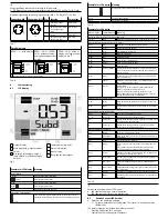
Displaying parameters (SHOW mode)
Requirement: The sensor is ready for operation (RUN mode).
8.3.1
Switching output OutA
•
Press the A pushbutton.
Ä
The first parameter set is displayed. [Fctn] flashes.
The following parameters can be displayed by repeatedly pressing the A pushbut-
ton
è
Fig.5. At the end, the min. and max. values are displayed. This can be reset
with the Edit pushbutton.
8.3.2
Switching output OutB or analogue output OutD
•
Press B pushbutton.
Ä
The first parameter set is displayed. [Fctn] with OutB or [Out] with OutD
flashes.
The following parameters are displayed by repeatedly pressing the B pushbutton
è
Fig.5.
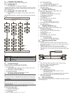
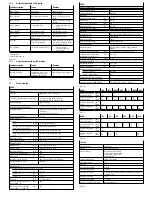
Fig. 5
Legend for
è
Fig.5
MIN, MAX
Parameter is displayed only for switching output OutA, without Timeout
Edit button
A or B pushbutton
Tab. 11
8.4
Entering the security code
The security code must be entered when "Lock" is active.
Requirement: The sensor is ready for operation (RUN mode).
1. Press the Edit button.
Ä
The EDIT mode is active. If the security code is activated, the parameter
entry option is blocked: [Lock] flashes.
2. Enter security code set with A or B pushbutton.
3. Press the Edit button briefly.
Ä
[OutA] flashes. The parameter entry option is unblocked.
8.5
Configuring switching output (EDIT mode)
The process is the same for configuring the switching outputs for OutA and OutB.
In the following, the process is described using the switching output OutA. Menu
structure
è
Fig.7
Changing the switching behaviour of the switching outputs in the EDIT mode is
effective immediately.
Requirement: The sensor is ready for operation (RUN mode).
Switching functions
è
6 Function
1. Press the Edit button briefly.
Ä
[Edit] appears. [OutA] flashes.
2. Press the Edit button briefly.
Ä
[Fctn] flashes.
3. With A or B pushbutton, select _I¯ or _I¯I_ or d_I¯I_.
4. Press the Edit button briefly.
Ä
–
The set value is saved.
–
The next adjustable parameter is shown.
5. Set the parameter with A or B pushbutton.
6. Repeat points 4 and 5 until all parameters are set
è
Fig.5.
7. Press the Edit button.
Ä
Switch to the RUN mode.
8.6
Set analogue output (EDIT mode)
Requirement: The sensor is ready for operation (RUN mode).
1. Press the Edit button briefly.
Ä
[Edit] appears. [OutA] flashes.
2. Select [OutD] with the A pushbutton or B pushbutton.
Ä
[Edit] appears. [OutD] flashes.
3. Press the Edit button briefly.
Ä
[Out] flashes.
4. Set the parameter with A or B pushbutton.
5. Press the Edit button briefly.
Ä
–
The set value is saved.
–
The next adjustable parameter is shown.
6. Repeat points 4 and 5 until all parameters are set.
7. Press the Edit button.
Ä
Switch to the RUN mode.
8.7
Change device settings (EDIT mode)
Requirement: The sensor is ready for operation (RUN mode).
1. Press the Edit button briefly.
Ä
[Edit] appears. [OutA] flashes.
2. With A or B pushbutton, select special menu [Spec].
Ä
[Spec] flashes.
3. Press the Edit button briefly.
Ä
[Filt] flashes.
4. Set the parameter with A or B pushbutton.
5. Press the Edit button briefly.
Ä
–
The set value is saved.
–
The next adjustable parameter is shown.
6. Repeat points 4 and 5 until all parameters are set.
8.8
Replicating parameters (EDIT mode)
Requirements:
–
The pre-configured master sensor is ready for operation (RUN mode).
–
Master sensor and device sensor have the same design regarding the para-
meters (same device ID).
–
The master sensor is connected with the device sensor
è
Fig.6.
–
Parameterisation of the device sensor must not be blocked via IO-Link.
–
The device sensor is in an unswitched status (switching output PNP, display
OutA off).
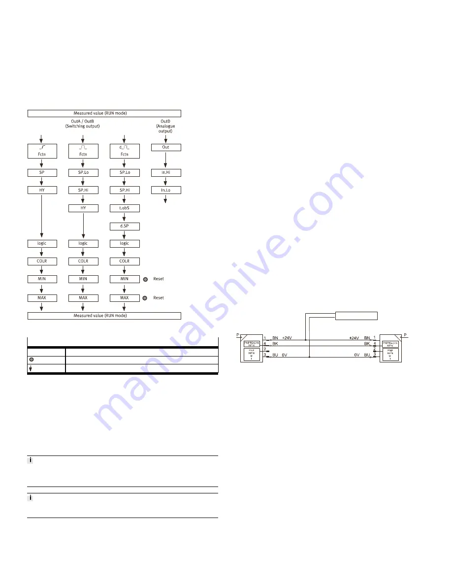
Spannungsversorgung
Master-Sensor
Device-Sensor
Fig. 6
1. Select special menu [Spec] at the master sensor via device settings.
2. Press the Edit button briefly until [MASt] appears.
3. With A or B pushbutton, select [ON].
4. Press the Edit button.
Ä
[REPL] / [RedY] appears.
5. Press A or B pushbutton.
Ä
–
[REPL] / [RUN] appears briefly.
–
The parameters are transmitted to the device sensor.
–
[REPL] / [RedY] appears.
If an error occurs, an error message appears
è
12 Fault clearance.
6. Repeat point 5 if an additional sensor should be parameterised.
7. Press the Edit button briefly.
Ä
Switch to the RUN mode.
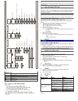
8.9
Menu structure (EDIT mode)
Some menu options or setting values are not applicable, depending on the selec-
ted switching function.


