
Translation of the original instructions
1
About this document
The operating instructions describe the entire function range. The function range
is limited, depending on the product variant. You can find detailed specifications
for the product, the device description file (IODD) with a description of the IO-Link
parameters and the declaration of conformity at
è
www.festo.com.
1.1
Further applicable documents
All available documents for the product
è
www.festo.com/pk.
2
Safety
2.1
Intended use
The pressure sensor SPAU is intended for monitoring pressure of compressed air
and inert gases in the piping.
2.2
General safety instructions
–
The product may only be used in its original status without unauthorised
modifications.
–
Only use the product if it is in perfect technical condition.
–
Take into consideration the ambient conditions at the location of use.
–
Operate the product only with compressed air of the specified air quality class
è
13 Technical data
–
Observe the specifications on the product labelling.
–
Comply with all applicable national and international regulations.
2.3
Area of application and approval
The information in this section, in combination with the UL marking on the
product, must be observed in order for there to be compliance with the certifica-
tion conditions of Underwriters Laboratories Inc. (UL) for USA and Canada.
UL approval information
Product category code
QUYX, QUYX7
File number
E322346
Standards taken into account
UL 61010-1
CAN/CSA C22.2 No. 61010-1
UL symbol
Tab. 1
The unit must be powered by a power source that fulfils the requirements of an
energy-limited circuit in accordance with IEC/EN/UL/CSA 61010-1 or a power
source with limited power (LPS) in accordance with IEC/EN/UL/CSA 60950-1 or
IEC/EN/UL/CSA 62368-1 or a Class 2 circuit in accordance with NEC or CEC.
3
Service
–
If you have technical questions, contact the regional Festo contact at
è
www.festo.com.
4
Accessories
–
Accessories
è
www.festo.com/catalogue.
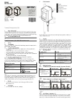
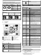
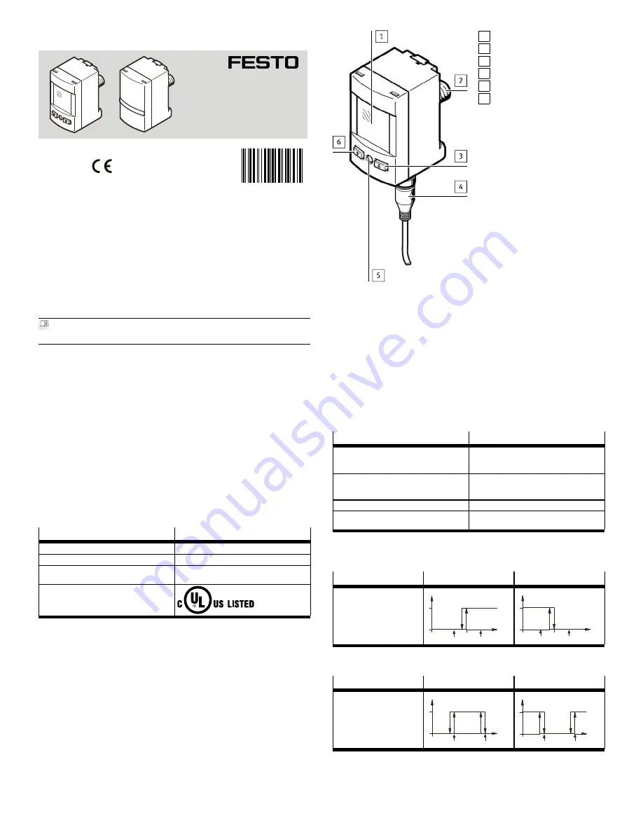
5
Product overview
1 Display
2 Pneumatic connection
3 B pushbutton
4 Electrical connection
5 Edit button
6 A pushbutton
Fig. 1 Display variant without front panel mounting. Representation of other vari-
ants can deviate from this.
6
Function
The sensor converts pneumatic pressure values (relative pressure) into electrical
signals, which can be used for control or regulating functions. Measurements are
carried out using a piezoresistive sensor element with a following electronic eval-
uation unit. Connection to the higher-level system is provided by 1 or 2 switching
outputs, an analogue output and/or an IO-Link interface. The switching outputs
can be configured for monitoring of a threshold value, a pressure range or a differ-
ential pressure. For each output, PNP or NPN and normally open (NO) or normally
closed (NC) can optionally be set. Through the IO-Link interface, process values
can be read out and parameters changed and transmitted to additional devices.
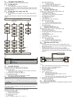
6.1
Operating statuses
Operating status
Function
RUN mode
–
Basic status after the operating voltage is
switched on
–
Display of the current measured value
SHOW mode
–
Display of the current settings
–
Display and resetting of the minimum and
maximum values
EDIT mode
Setting or modification of parameters
TEACH mode
Acceptance of the current measured value to
determine switching points
Tab. 2
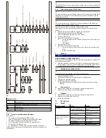
6.2
Switching functions
6.2.1
Threshold value comparator for monitoring of a pressure threshold _|¯
Function
NO (normally open)
NC (normally closed)
Switching function:
–
1 switching point (SP)
TEACH mode:
–
2 Teach points (TP1, TP2)
–
SP = ½ (TP1+TP2)
TP1 TP2
HY
1
0
Out
p
SP
TP1 TP2
SP
HY
1
0
Out
p
Tab. 3
6.2.2
Window comparator for monitoring of a pressure range _|¯|_
Function
NO (normally open)
NC (normally closed)
Switching function:
–
2 switching points (SP.Lo,
SP.Hi)
TEACH mode
1)
:
–
2 Teach points (TP1, TP2)
–
TP1 = SP.Lo, TP2 = SP.Hi
HY HY
TP1=SP.Lo TP2=SP.Hi
1
0
Out
p
HY HY
TP1=SP.Lo TP2=SP.Hi
1
0
Out
p
1) SP.Lo = smaller pressure/vacuum value, SP.Hi = larger pressure/vacuum value, dependent on the Teach
sequence
Tab. 4
6.2.3
Auto difference monitoring d_|¯|_
This function permits monitoring of a pressure value for constancy. The applied
pressure is constant in the range between [SP.Lo] and [SP.Hi], so the reference
pressure P
Ref
is automatically determined. The result is a switching operation at
8035290
SPAU
Pressure sensor
8035290
2018-06a
[8035292]
Instructions | Operating
Festo AG & Co. KG
Ruiter Straße 82
73734 Esslingen
Germany
+49 711 347-0
www.festo.com