8.7
Change device settings (EDIT mode)
Requirement: The sensor is ready for operation (RUN mode).
1. Press the Edit button briefly.
Ä
[Edit] appears. [OutA] flashes.
2. Select the Special menu [Spec] using the A or B pushbutton.
Ä
[Spec] flashes.
3. Press the Edit button briefly.
Ä
[Filt] / [MSEC] flashes.
4. Set the parameter with A or B pushbutton.
5. Press the Edit button briefly.
Ä
The set value is saved. The next adjustable parameter is shown.
6. Repeat steps 4 and 5 until all parameters are set.
8.8
Setting the volume pulse output (EDIT mode)
Requirement: The sensor is ready for operation (RUN mode).
1. Press the Edit button briefly.
Ä
[Edit] appears. [OutA] flashes.
2. Select [Puls] using the A or B pushbutton.
3. Press the Edit button briefly.
Ä
[SP] / [Volume Unit] flashes.
4. Set the parameter with A or B pushbutton.
5. Press the Edit button briefly.
Ä
The set value is saved. The next adjustable parameter is shown.
6. Repeat steps 4 and 5 until all parameters are set.
8.9
Set analogue output (EDIT mode)
Requirement: The sensor is ready for operation (RUN mode).
1. Press the Edit button briefly.
Ä
[Edit] appears. [OutA] flashes.
2. Select [Anlg] using the A or B pushbutton.
3. Press the Edit button briefly.
Ä
[Out] / [V] flashes.
4. Set the parameter with A or B pushbutton.
5. Press the Edit button briefly.
Ä
The set value is saved. The next adjustable parameter is shown.
6. Repeat steps 4 and 5 until all parameters are set.
8.10
Replicating parameters (EDIT mode)
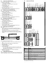
Requirement:
–
The pre-configured master sensor is ready for operation (RUN mode).
–
Master sensor and device sensor have the same design regarding the para-
meters (same device ID).
–
The master sensor is connected with the device sensor
è
–
Parameterisation of the device sensor must not be blocked via IO-Link®.
–
The device sensor is in an unswitched status (switching output PNP, display
OutA off).
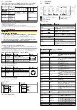
Fig. 11 Example of pin allocation SFAH-...M8
1. Select the Special menu [Spec] on the master sensor through the device set-
tings.
2. Press the Edit button briefly several times until [MASt] appears.
3. Select [ON] using the A or B pushbutton.
4. Press the Edit button.
Ä
[REPL] / [RedY] appears.
5. Press A or B pushbutton.
Ä
[REPL] / [RUN] appears briefly. The parameters are transmitted to the
device sensor. [REPL] / [RedY] appears. If an error occurs, an error mes-
sage appears
è
6. Repeat point 5 if an additional sensor should be parameterised.
7. Press the Edit button briefly.
Ä
Switch to the RUN mode.
8.11
Configuring the sensor (EDIT mode)
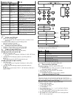
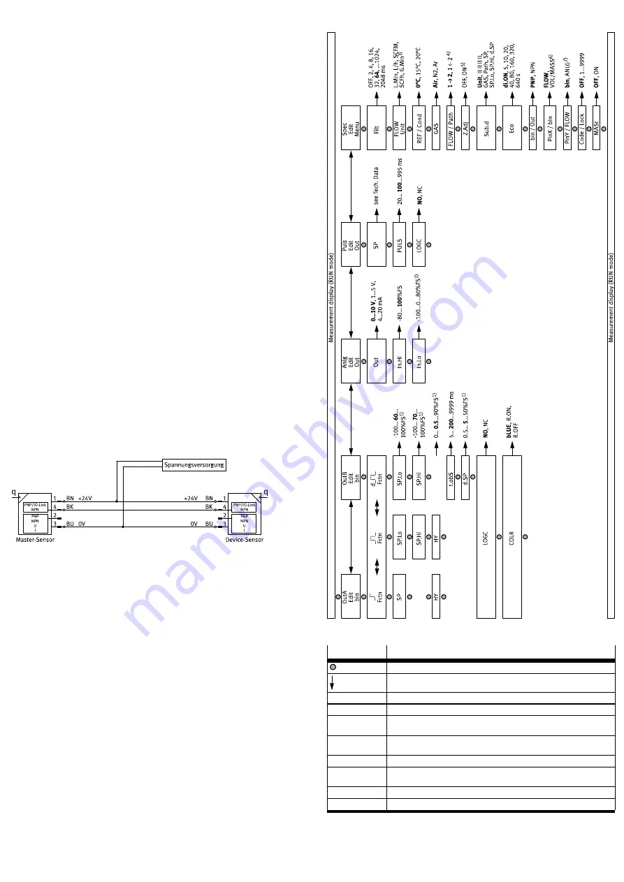
shows the complete menu structure. Some menu options or setting values are not
applicable, depending on the product variant and the selected switching function.
8.12
Menu structure (EDIT mode)
Fig. 12 Menu structure of Edit mode
Legend
Meaning
Edit button
A or B pushbutton
Bold
Factory setting
1)
The values refer to the respective measuring range and selected unit
2)
Factory setting –100 for bidirectional variant; factory setting 0 for unidirection-
al variant
3)
Factory setting l/h for measurement ranges 0.1 l/min and 0.5 l/min; factory
setting l/min for all other measurement ranges
4)
Menu option only for bidirectional variant
5)
Factory setting OFF for unidirectional variant; factory setting ON for bidirection-
al variant
6)
For M8 plug: pin 4; for L1 plug: pin 2
7)
For M8 plug: pin 2; for L1 plug: pin 3
Tab. 17 Legend for menu structure

