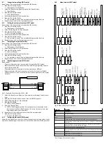
8.13
Teach switching points (TEACH mode)
The Teach process is the same for configuring the switching outputs for OutA and
OutB. In the following, the process is described using the switching output OutA.
The Teach function is only available for flow monitoring.
Requirement: The sensor is ready for operation (RUN mode).
If the security code is activated, the parameter entry option is blocked: [Lock]
flashes.
1. Enter the security code
è
8.5 Enter the security code (EDIT mode).
2. Establish the switching function in EDIT mode
è
8.6 Configuring switching output (EDIT mode).
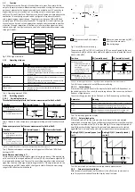
3. Apply signal value 1.
4. Press the A pushbutton and Edit button.
Ä
The current signal value will then be adopted as the first Teach point
(TP1). [t-IN] flashes.
5. Apply signal value 2.
6. Press the A pushbutton and Edit button.
Ä
The current signal value will then be adopted as the first Teach point
(TP2). Switch to the RUN mode.
8.14
Zero point synchronisation (Zero Adjust)
Requirement:
–
The sensor is ready for operation (RUN mode).
–
The operating pressure is present, but no flow rate exists.
–
[Z.AdJ] is set to [ON] (
è
8.7 Change device settings (EDIT mode)).
–
The measured value lies in the range 0 l/min ± 3 %FS.
•
Press the A and B pushbuttons and Edit button simultaneously.
Ä
–
If [OK] appears: the zero point synchronisation was successful.
–
If [FAIL] appears: the zero point synchronisation was not successful.
Check requirements.
If [Z.AdJ] [OFF] is set for a later time, the sensor takes over the factory setting cal-
ibration values.
9
Operation and use
After the supply voltage is switched on, the SFAH needs a warm-up time of
10 minutes until it achieves the specified accuracy.
The flow rate displayed by the SFAH refers to the standard conditions that were
set under Options in the Special menu.
9.1
Restoring factory settings (restore)
By resetting to the factory settings, the current settings are lost. If required, make
a note of these settings before resetting.
1. Switch off operating voltage.
2. Keep the A and B pushbuttons pressed down simultaneously.
3. Switch on the operating voltage.
4. Additionally, press the Edit button.
Ä
[RSto PArM] appears. All parameters are reset to the factory settings.
10
Maintenance and care
1. Turn off energy source and compressed air.
2. Clean sensor with non-abrasive cleaning agents.
11
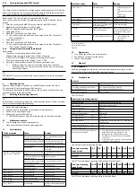
Fault clearance
Fault description
Cause
Remedy
No operating voltage or imper-
missible operating voltage
Apply permissible operating
voltage.
Electrical connections swapped
Connect the device in accord-
ance with the circuit diagram.
Device defective
Replace device
No display
Eco mode on
Press pushbutton or switch off
Eco mode
Short circuit or overload at the
output
Eliminate short circuit/over-
load.
Incorrect switching point taught
(e.g. at 0 l/min)
Repeat teaching.
Incorrect standard condition set
for volumetric flow rate
Correct standard condition
Device defective
Replace device
Indicator or switching output
does not react as expected
Parameter incorrect
Reset to factory settings.
[Er01] / [FAIL]
1)
Device defective
Replace device
[Er02] / [ASIC]
1)
Device defective
Replace device
[Er03] / [SEnS]
1)
Device defective
Replace device
[Er09] / [UndR]
Below sensing range
Maintain sensing range
[Er10] / [OVER]
Sensing range exceeded
Maintain sensing range
[Er17] / [SUPL]
2)
Undervoltage
Maintain permissible operating
voltage
Fault description
Cause
Remedy
[Er20] / [t.Hi]
2)
Temperature fault
–
Check operating condi-
tions
–
Check ambient temperat-
ure
–
Check wiring
–
Replace device
[Er21] / [SHRt]
2)
Short circuit at OutA/“Puls”
Eliminate short circuit
[Er22] / [SHRt]
2)
Short circuit at OutB
Eliminate short circuit
[Err] / [bUSY]
OutA/“Puls” is switched active
in the device sensor
Check device settings
[Err] / [Id]
Device ID error, devices do not
have the same design
When replicating, use sensor
with the same type flow rate
measurement range (same
device ID)
[Err] / [COM]
IO-Link® communication error
–
Check settings of the
device sensor
–
Check line
1) Display flashes red
2) Display illuminates red
Tab. 18
12
Disassembly
1. Turn off energy source and compressed air.
2. Separate connections from the sensor.
3. Loosen the mountings.
13
Disposal
ENVIRONMENT!
Send the packaging and product for environmentally sound recycling in accord-
ance with the current regulations
è
14
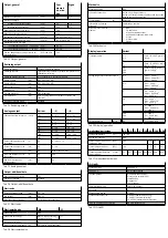
Technical data
General
Approvals
RCM compliance mark
CE marking (declaration of conformity
è
www.festo.com/sp)
In accordance with EU EMC Directive
In accordance with EU RoHS Directive
Information on materials
RoHS-compliant
Tab. 19 General
Input signal/measuring element
Measured variable
Volumetric flow rate, mass flow rate
Flow direction
Unidirectional, bidirectional
Measuring principle
Thermal
Warm-up time
[min]
10
Method of measurement
Heat transfer
Operating pressure
[bar]
–0.9 … 10
Operating pressure
[kPa]
–90 … 1000
Operating medium
Compressed air according to ISO 8573-1:2010 [6:4:4],
nitrogen, argon
Temperature of medium
[°C]
0 … 50
Ambient temperature
[°C]
0 … 50
Nominal conditions for determination of
the accuracy specification.
–
Operating pressure at output: 0 kPa relative
–
Medium and ambient temperature: 23°C
–
Analogue output: voltage with 20 kΩ load
–
Switching output: load current in the switched
status 5 mA
–
Mounting position: horizontal, display upwards
–
Inflow:
è
Tab. 20 Input signal/measuring element
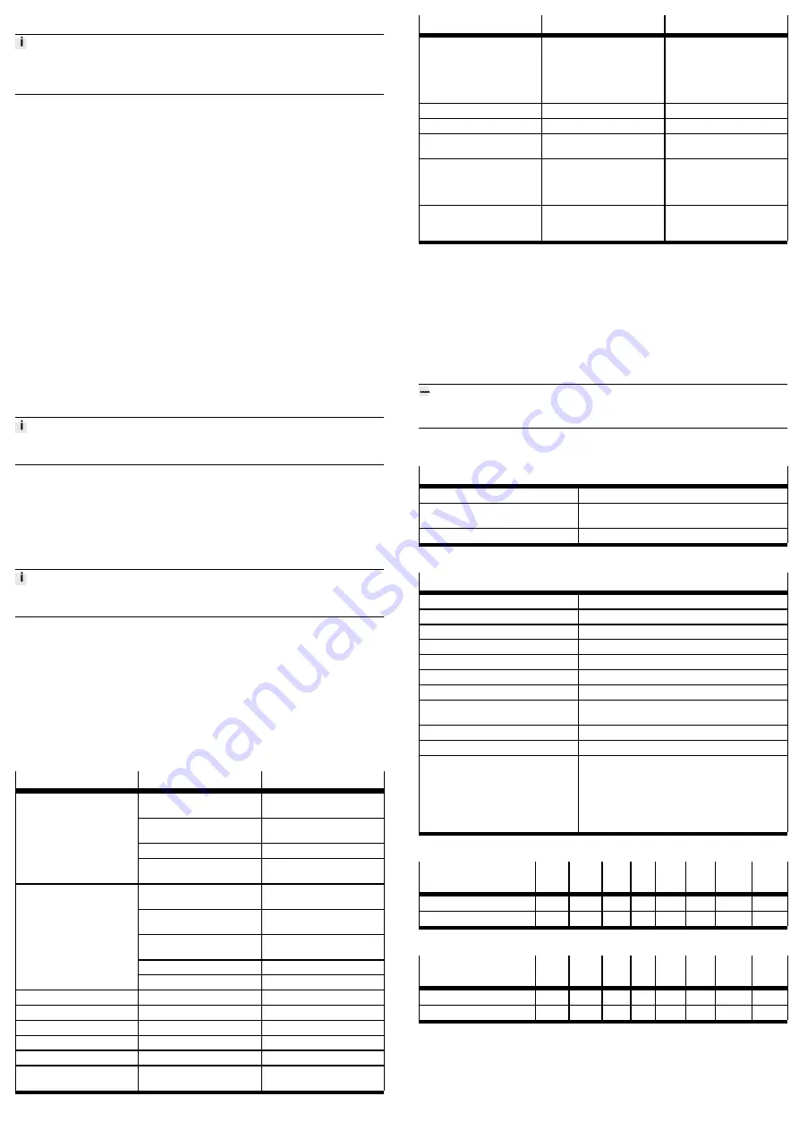
Flow rate measuring
range [l/min]
0.1
0.5
1
5
10
50
100
200
Start value
0.002
0.01
0.02
0.1
0.2
1
2
4
End value
0.1
0.5
1
5
10
50
100
200
Tab. 21 Flow rate measuring range unidirectional or bidirectional
Flow rate measuring
range [l/min]
0.1B 0.5B 1B
5B 10B 50B 100B 200B
Start value
–0.002
–0.01
–0.02 –0.1
–0.2
–1
–2
–4
End value
–0.1
–0.5
–1
–5
–10
–50
–100
–200
Tab. 22 Flow rate measuring range bidirectional, additional

