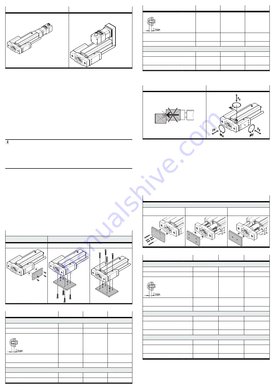
Axial kit EAMM-A
Parallel kit EAMM-U
Mount the motor only on a side without a guide
rod.
Tab. 2: Overview of motor mountings
Requirement
–
Only loosen screws or threaded pins that are described in the directions in the
instruction manuals.
–
Sufficient space for reaching and mounting the sealing air connection
1. Select the motor and motor mounting kit from
Festo
If other motors are used: observe the critical limits for forces, torques and
velocities.
2. Fasten motor mounting kit, observe instruction manual
3. Fasten the motor without tension. Support large and heavy motors.
Connect motor cables only on completion of mounting.
6.4
Fasten cylinder with guide
High mechanical loads on the mounting connections
If high parallel torques are applied to the drive system at the same time, this will
result in high mechanical loads at the mounting interfaces.
• If the mounting position is inclined or horizontal with direct fastening, the drive
system will require additional support near the motor mounting.
Requirement
–
No collision in the range of motion of the attachment component with motor,
mounting components and sensor components.
–
Sufficient space to reach maintenance interfaces.
–
Sufficient space for reaching and mounting the sealing air connection.
–
Flat mounting surface maximum 0.2 mm over the stroke length of the bearing
surface.
–
No distortion or bending when installing the product.
1. Select mounting attachments
2. Place the mounting attachments on the support points.
3. Tighten retaining screws.
Observe the maximum tightening torque and screw-in depth.
For additional information, contact your local Festo Service.
Direct fastening
Guide housing, lateral
Guide housing, bottom
Mounting via thread
Mounting via thread
Mounting via through-hole
Tab. 3: Overview of mounting components for profile
Size
32
45
60
Direct fastening, lateral via thread
Screw
M5
M5
M5
Max. tightening torque
[Nm]
5.2
5.2
5.2
Max. screw-in depth t
max
[mm]
8.5
12
10
Centring hole and centring
element
[mm]
Æ
7
Æ
7
Æ
7
Centring hole tolerance
H8
H8
H8
Direct fastening, bottom via thread
Screw
M5
M5
M5
Max. tightening torque
[Nm]
5.2
5.2
5.2
Size
32
45
60
Max. screw-in depth t
max
[mm]
12
12
10
Centring hole and centring
element
[mm]
Æ
7
Æ
7
Æ
7
Centring hole tolerance
H8
H8
H8
Direct fastening, bottom via through-hole
Screw
M4
M5
M6
Centring hole and centring
element
[mm]
Æ
4
Æ
5
Æ
7
Centring hole tolerance
H8
H8
H8
Tab. 4: Information for mounting components
6.5
Mounting attachment component
Collision-free
Guide load
Tab. 5: Requirement for attachment components
Requirement:
–
No collision in the range of motion of the attachment component with motor,
mounting components and sensor components.
–
Minimise guide load. Short lever arms from the centre of the yoke plate
to the force application points and centre of gravity of the attachment compo-
nents.
1. Select accessories
2. Place centring components in centring holes.
3. Position attachment component on the yoke plate.
4. Tighten retaining screws.
Observe the maximum tightening torque and screw-in depth.
Direct fastening
Yoke plate
Mounting via thread
Mounting via through-hole,
outside
Mounting via through-hole,
inside
Tab. 6: Overview of attachment components
Size
32
45
60
Direct fastening via thread
Screw
M3
M3
M4
Max. tightening torque
[Nm]
1.2
1.2
2.8
Max. screw-in depth t
max
[mm]
7
7
9
Centring hole and centring
element
[mm]
Æ
7
Æ
7
Æ
7
Centring hole tolerance
H8
H8
H8
Direct fastening via through-hole, outside
Screw
M4
M5
M5
Centring hole and centring
element
Æ
7
Æ
7
Æ
7
Centring hole tolerance
H8
H8
H8
Direct fastening via through-hole, inside
Screw
M4
M5
M5
Centring hole and centring
element
Æ
7
Æ
7
Æ
7
Centring hole tolerance
H8
H8
H8
Tab. 7: Information on attachment components


