1.4 Obligations of the operator for the safety function
The implemented safety function must be subjected to a regular and documented
performance test by a specialist during the period of use of the machine. The fre
quency of these tests must be determined by the machine operator based on the
specifications of the machine manufacturer.
Check the EMCA at least once per year.
2
Requirements for product use
Provide the complete product documentation to the following personnel:
– the design engineer and the installer of the machine or system
– the personnel responsible for commissioning
Store the documentation throughout the entire product lifecycle.
Ensure compliance with the specifications in this documentation. Also observe
the information in the documentation for the other components and modules
(e.g. axial kit, gear unit, actuator, lines).
Comply with all of the legal regulations that are applicable for the destination,
as well as the following documents:
– regulations and standards
– regulations of the testing organisations and insurers
– national specifications
For correct and safe use of the STO function:
Conduct a risk evaluation for your machine.
Comply with the specified safety characteristics (
è
Range of application and certifications
The EMCA with integrated STO safety function is a safety-related part of control
systems. The product has the CE marking. Certain configurations of the product
have been certified by Underwriters Laboratories Inc. (UL).
Certificates and declaration of conformity for the product
è
www.festo.com/sp.
Specified directives and standards
Version statuses
2006/42/EC
ENISO13849-1:2008-06/AC:2009-03
EN62061:2005-04
2014/30/EU
EN 61800-5-2:2007-10
-
2.1 Transport and storage conditions
Protect the product during transport and storage from excessive stress factors.
Excessive stress factors include:
– mechanical stresses
– impermissible temperatures
– moisture
– aggressive atmospheres
Store and transport the product in its original packaging. The original packaging
offers sufficient protection from typical stresses.
2.2 Technical prerequisites
For correct and safe use of the product:
Comply with the specified connection and ambient conditions for all of the con
nected components
è
Chapter 9. Only compliance with the limit values or load
limits will enable operation of the product in compliance with the relevant safety
regulations.
3
Product description
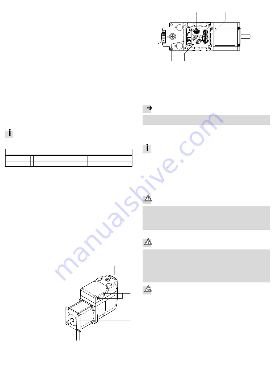
3.1 Product overview
1
[X1]: Parameterisation
interface (Ethernet
interface)
2
LED light guide (6x) –
2 used
3
Cable throughfeeds
(6x)
4
Motor flange
5
Through-hole for
mounting (4x)
6
Mounting thread (4x)
thread M4
7
Shaft
8
Cover
1
2
3
4
5
7
6
8
View with open cover
1
2
3
4
5
6
7
8
9
aJ
1
[X5]: Braking resistor
2
[X10]: External battery (...-1TM)
3
[X6]: STO interface
4
[X9]: I/O interface
5
[X8]: Reference or limit switch 1
6
[X7]: Reference or limit switch 2
7
FE connection (flat plug)
8
[X4]: Power supply
9
OK LED (green)
aJ
ERROR LED (red)
4
Mounting
Note
Excessive axial and radial forces on the motor shaft can damage the motor.
Comply with maximum permissible shaft loads (
è
The mounting flange offers the following options for fastening:
– Fastening via 4 through-holes for screws of size M6
– Fastening via 4 female threads of size M4 (screw-in depth [mm]: 5).
Observe the assembly instructions for the additional components used
(e.g. axial kit, parallel kit, gear unit, shaft).
The drive must be mounted securely and free of tension.
1. Move the slide or cantilever of the driven mechanical system into a safe posi
tion.
2. Connect the EMCA to the driven mechanical system (
è
Assembly instructions
of the additional components used).
3. Tighten the mounting screws (4x). Tightening torque
è
Assembly instructions
of the additional components used.
5
Electrical installation
Caution
Unexpected and unintended movement of the drive during mounting, installation
and maintenance work.
Before starting work: Switch off
power supplies. Removal of the enable signal
at the EMCA is not sufficient.
Secure the power supplies against accidental reactivation.
5.1 Connections and cables
Caution
Unexpected and unintended movement of the drive as a result of incorrectly
assembled cables.
Only use the plug connectors provided and preferably the cables listed in
the specified accessories
è
www.festo.com/catalogue.
Lay all flexible cables so that they are free of kinks and mechanical stress,
e.g. in an energy chain. Observe the instructions for the axis and the additional
components.
ESD protection
At unassigned plug connectors, there is the danger that damage may occur to
the product or to other system parts as a result of ESD (electrostatic dis
charge).
Comply with the handling specifications for electrostatically sensitive
devices.
Seal unassigned plug connectors with protective caps.
Earth system parts prior to installation.
Use appropriate ESD equipment (e.g. shoes, earthing straps).
The plugs for the connectors are included in the scope of delivery (assortment of
plugs NEKM-C).


