


Automatic Saving of Device Data
Changes to device data are automatically saved permanently (flash memory). The
flash memory is designed for 100,000 write cycles. Frequent changes to the
device data (e.g. when using the device for positioning tasks via IO-Link) can
cause damage to the device.
Every time the logic voltage is switched on, the position of the reference end posi-
tion "Ref" is re-initialised with Speed Ref with the first motion task. When moving
to the Lim
Out
end position, the Lim
Out
end position is approached at
the Speed Out velocity.
End-to-end operation
Parameterise end-to-end operation
HMI:
–
Speed Out, Speed In, Force and Start Press
è
10.3 Display and operating components (HMI)
IO-Link (acyclic device data):
–
Velocity Speed Out: 0x0101.0, Speed Out
1)
–
Velocity Speed In: 0x0100.0, Speed In
1)
–
Force/Torque: 0x0102.0, Force
1)2)
–
Start Press Position Pos
Start Press
: 0x0105.0, Position Start Press [mm]
2)3)4)
–
End position Lim
Out
: 0x0106.0, end position Out [mm]
4)
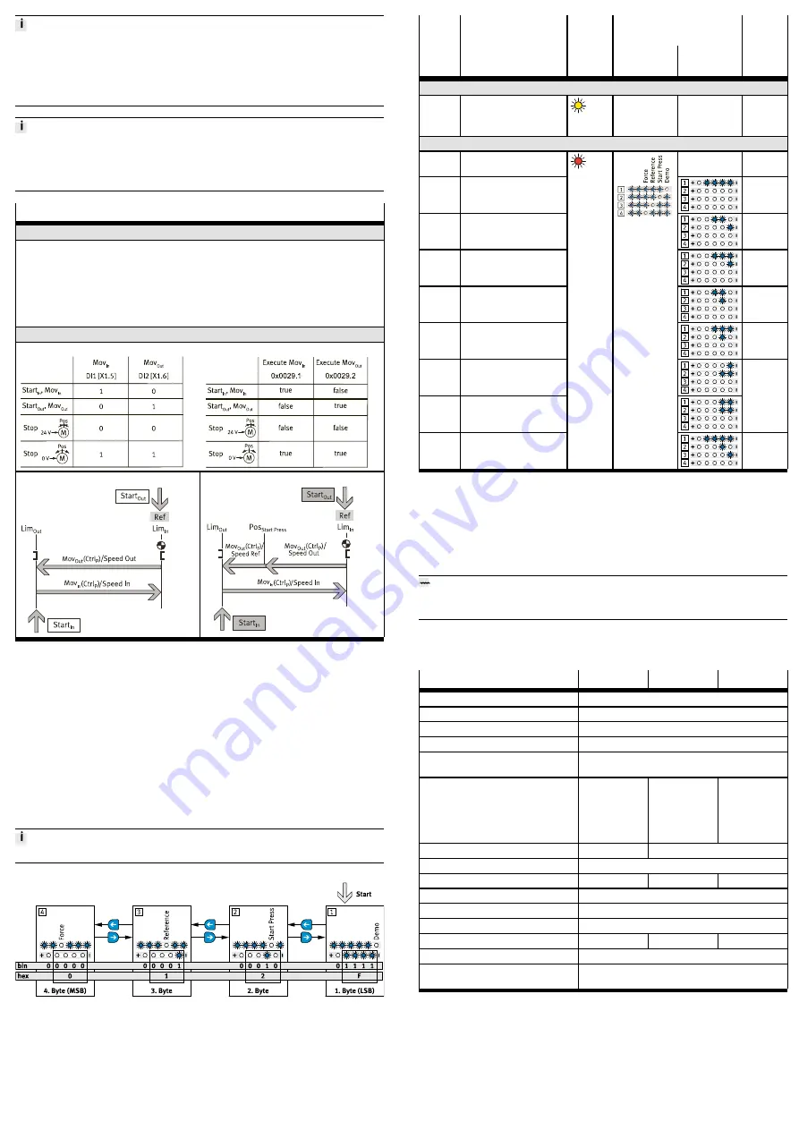
Control end-to-end operation
DIO:
IO-Link (cyclic process data):
Single end-to-end operation
End-to-end operation with press function
1) 10, 20, ..., 100% of maximum value
2) Only required for end-to-end operation with press function
3) Reset with every homing
4) reference point: reference end position "Ref"
Tab. 4 Parameterising and controlling end-to-end operation
11
Malfunctions
"Warnings and Errors" diagnostic messages are displayed by the LED C/Q and
menu and parameters LED displays.
In DIO mode, errors are reported to the controller via the sensor signal combina-
tion "1–1".
Errors can be reset as follows:
–
DIO mode
è
reset of logic voltage
–
IO-Link operation
è
parameter "Quit Error" (0x0029.3 or 0x0107.0)
The first error that occurred is always displayed.
Fig. 9 Display of diagnostic messages (example)
Error
code
Description
LED
LED displays
Event
code
hex
(dec)
C/Q
Open
Parameter
(IO-
Link)
Warning
z
Warnings
1)
yellow
light
z
z
0x...
Error
z
Common device error
è
Contact Festo
…
0x1000
0x000F
(15)
I
2
t monitoring power stage
error
0x1805
0x0016
(22)
Logic voltage
undersupply
2)
0x1804
0x0017
(23)
Logic voltage oversupply
0x1803
0x0026
(38)
Load voltage undersupply
or not connected
0x1802
0x0027
(39)
Load voltage oversupply
0x1801
0x0031
(49)
Device undertemperature
0x0033
(51)
Device overtemperature
0x4000
0x012F
(303)
IO-Link connection lost
red light
z
1) Additional information
è
Description of integrated drive EMCS-ST
2) This error can only be acknowledged by a restart.
Tab. 5 "Warnings and Errors" diagnostic messages
11.1
Repair
Send the product to the Festo repair service for repair.
12
Disposal
ENVIRONMENT!
Send the packaging and product for environmentally sound recycling in accord-
ance with the current regulations
è
13
Technical data
Additional information
è
Size
25
45
60
Mounting position
Any
Ambient temperature
[°C]
0 … +50
Storage temperature
–20 … +60
Degree of protection
IP40
CE marking
è
Declaration of Conformity
in accordance with EU EMC Directive
in accordance with EU RoHS Directive
Max. payload
–
horizontal mounting
position
[kg]
2
10
20
–
vertical mounting posi-
tion
[kg]
2
5
13
Max. velocity
1)
[mm/s]
180
250
Velocity "Speed Press"
[mm/s]
10
Max. feed force
2)3)
[N]
40
100
200
Acceleration/deceleration
[m/s
2
]
5
Duty cycle
[%]
100 (+30 … +50 °C: – 2% per kelvin)
Distance stop/end position
4)
[mm]
1
Repetition accuracy
[mm]
±0.015
±0.015
±0.01
Nominal voltage
[V DC]
24
Logic current consumption
(logic, pin 1)
[mA]
DIO operation: 100 ... 300
IO-Link operation: 100 ... 150
1) Maximum value for Speed In/Speed Out at level 10
2) Maximum value for force at level 10
3) The force is controlled and evaluated by regulating the motor current. Depending on the mechanism of the
drive, a linear force can be determined from the level of current measured. The target is set as a percent-
age of the rated motor current and may deviate from the actual force on the axis. In the case of low force
levels, the influence of friction in the system on the running behaviour and the actual force on the axis
must also be taken into account.
4) Distance (MechIn – LimIn or MechOut – LimOut)
Tab. 6 Technical data ELGS-BS