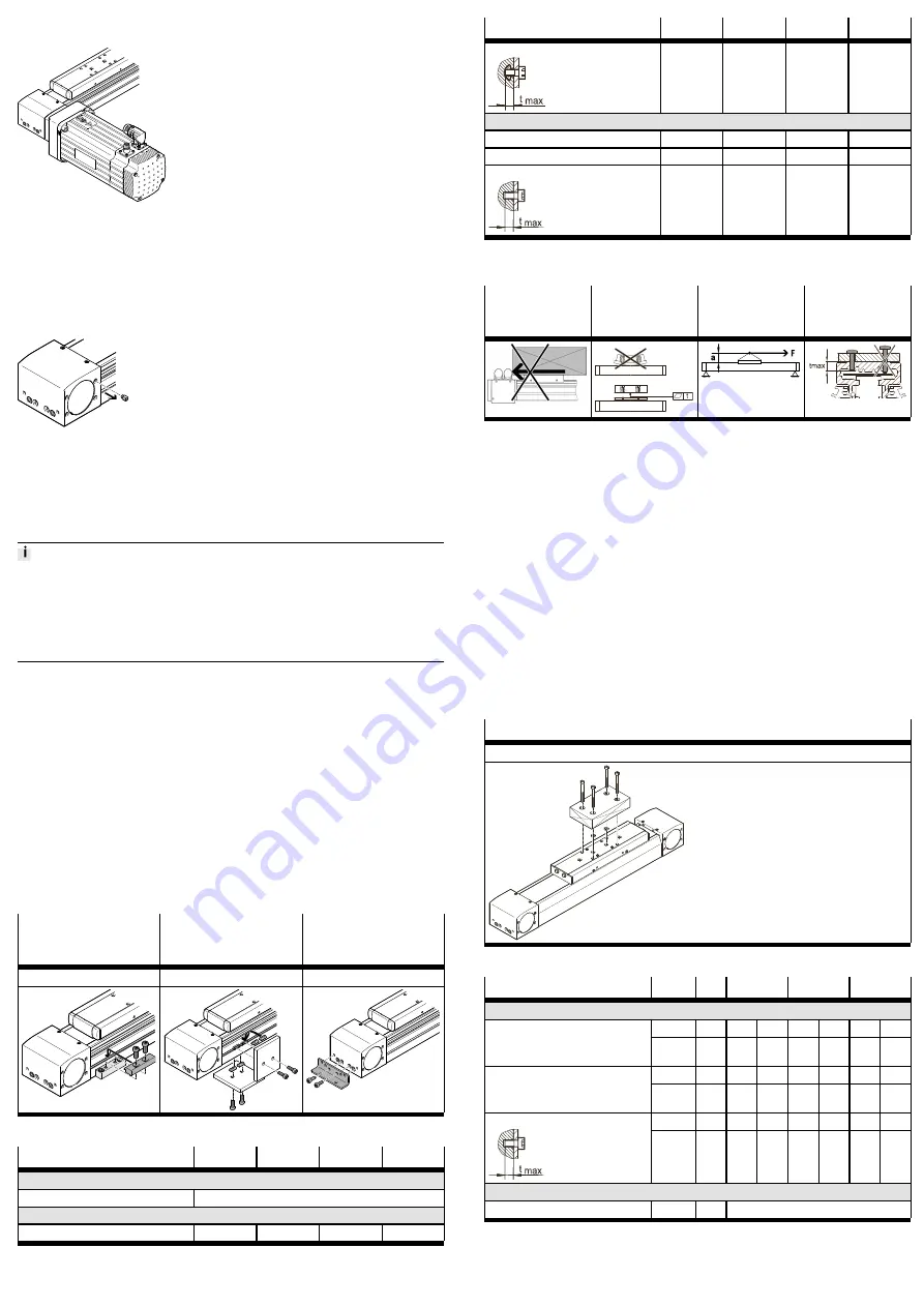
7.3
Mounting the motor
Fig. 3 Motor mounting
Only loosen screws or threaded pins that are described in the directions in the
instruction manual.
1. Select the motor and motor mounting kit from
Festo
è
When using other motors: observe the critical limits for forces, torques and
velocities.
Fig. 4 Remove the plug screw
2. Remove the sealing air plug screw from the threaded hole.
3. Fasten motor mounting kit, observe instructions
è
4. Fasten the motor without tension. Support large and heavy motors.
Connect motor cables only on completion of mounting.
7.4
Fasten axis
High mechanical loads on the mounting connections
If the mounting position of the motor and the mounting component simultan
eously cause high rectified torques around the longitudinal axis, this leads to high
mechanical loads at the mounting interfaces.
•
The foot mounting HPE should only be used in combination with the profile
mounting MUE or the slot nuts NST.
Requirement
–
No collision in the movement space of the attachment component with motor,
mounting and sensor components.
–
Sufficient space to reach maintenance interfaces.
–
Flatness of the mounting surface of 0.05% of the stroke length or max.
0.5 mm over the stroke length of the bearing surface.
–
Required support points lie within the specified support
distances
è
–
No distortion or bending when installing the product.
1. Select mounting attachments
è
2. Place the mounting attachments on the support points.
3. Tighten retaining screws.
Observe max. tightening torque and max. screwin depth.
For area and 3dimensional gantries, pay attention to parallelism, product height
and alignment of the axes.
For additional information, contact your local Festo Service.
Profile mounting MUE
(ELGA-...-...MA)
Slot nut NST For mount-
ing slot
(ELGA-...-...NM)
Foot mounting HPE
(ELGA-...-MF)
Mounting via profile groove
Mounting via profile groove
Mounting via thread
Tab. 1 Overview of mounting components
Size
70
80
120
150
Profile mounting MUE
Screw
Instruction manual
è
Slot nut NST
Screw (side/bottom)
M5
M5
M6
M6
Size
70
80
120
150
max. screwin depth t
max
[mm]
6
6
12
12
Foot mounting HPE
Screw
M5
M5
M8
M8
max. tightening torque
[Nm]
5.9
5.9
24
24
max. screwin depth t
max
[mm]
10
10
16
18
Tab. 2 Information on mounting attachments
7.5
Mounting attachment component
Collision-free
Evenness
Centre of gravity
and tilting
moment
Max. screw-in
depth
Tab. 3 Requirement for attachment element
Requirement
–
No collision in the movement space of the attachment component with motor,
mounting and sensor components.
–
Flatness of the mounting surface of the mounting component of 0.01 mm
(recirculating ball bearing guide KF/roller guide RF) or 0.03 mm (plainbearing
guide G) over the slide surface.
–
Position of the centre of gravity and tilting moment (force F parallel to the axis
of motion) of the attachment component centrally on the slide and close to
the slide surface (short lever arm a).
–
The maximum screwin depth of the retaining screws is not exceeded.
1. Select accessories
è
2. Place centring components in centring holes.
3. Position the attachment component on the slide.
4. Tighten retaining screws.
Observe max. tightening torque and max. screwin depth.
When using an additional external guide, ensure exact parallelism and alignment
of the axes and guide.
Recommendation: use guide fixings with tolerance compensation.
Direct mounting
Mounting via thread
Tab. 4 Overview of attachment component
Size
70
80
120
150
Direct mounting
G/RF
M5
M5
M6
M5
M6
M6
M8
Screw
KF
M5;
M6
M5
M6
M5
M6
M6
M8
G/RF
5.9
5.9
9.9
5.9
9.9
9.9
24
Tightening torque
[Nm]
KF
5.9;
9.9
5.9
9.9
5.9
9.9
9.9
24
G/RF
7.5
9
9.7
9.7
12.6
11
10.7
max. screwin depth t
max
[mm]
KF
7.5;
5.4
9
9.7
9.7
12.6
11
10.7
Centring (bore tolerance H7)
Centring pins
[mm]
G/KF
Æ
5
–


