11
Disassembly
WARNING!
Danger of crushing! Uncontrolled advance of piston rod.
When the energy supplies are switched off, if the compressed air supply is
switched off first and only then the operating voltage, in case of a fault
(e.g. defective valve block) there may be continuous excess pressure in a cylinder
chamber. The piston rod may then advance unexpectedly during disassembly and
crush body parts.
Switch off the energy supplies in the following sequence to ensure that the integ
rated valve block can safely exhaust the drive:
•
First switch off the operating voltage supply.
•
Only then switch off the compressed air supply.
WARNING!
Danger from parts flying through the air!
If there is still excess pressure in a cylinder chamber despite the compressed air
supply being switched off, when a cylinder end cap is loosened it may fly off sud
denly through the air and injure people.
•
Do not dismantle the cylinder end cap! The product must be overhauled by
the Festo repair service only.
1. First switch off the operating voltage supply and then the compressed air sup
ply so that the integrated valve block exhausts the drive.
2. Disconnect the slider gate from the piston rod.
3. Loosen the screws on the flange of the process valve or shutoff weir.
4. Remove drive (along with mounting adapter and coupling extension if neces
sary).
12
Disposal
–
Observe the local regulations for environmentally friendly disposal.
–
Dispose of the product in an environmentally friendly manner. When doing
this, also take residual media into account (recycling of hazardous waste
where appropriate).
13
Technical Data
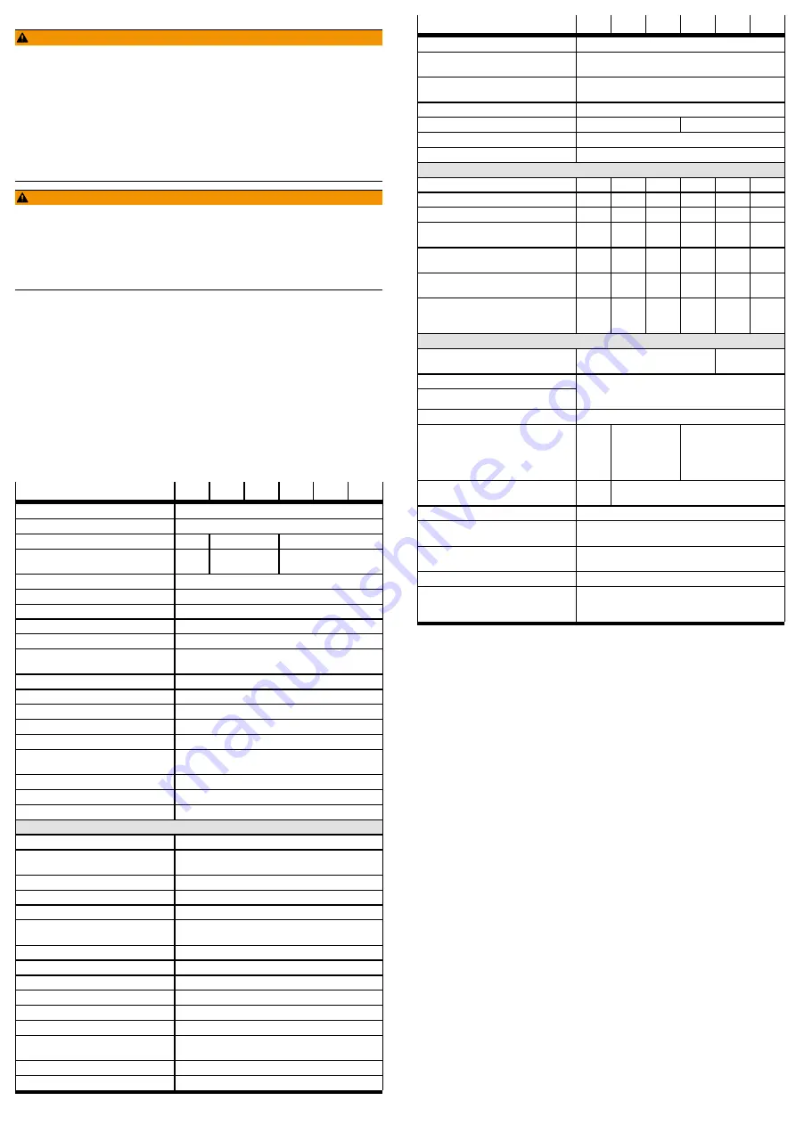
DFPI-...-ND2P-C1V-...-A
-100
-125
-160
-200
-250
-320
Based on standard
DIN 3358
Type of mounting
On flange to DIN 3358
Flange hole pattern
F07
F10
F10, F14
Spanner size on the piston
rod
22
27
36
Constructive design
Piston rod, cylinder barrel
Cushioning
No cushioning
Mounting position
Any
Mode of operation
Doubleacting
Position detection
With integrated displacement encoder
Measuring principle of dis
placement encoder
Potentiometer
Positioning accuracy
[% FS]
1
Repetition accuracy
[% FS]
±1
Hysteresis
[% FS]
±1
Size of dead space
[% FS]
1
Accuracy of analogue output
[% FS]
±1
Analogue output response
time
[ms]
<
100
Analogue output load
[Ω]
600 (maximum)
Analogue input load
[Ω]
500 (maximum)
Electrical connection
5pin; straight plug; screw terminal
Pneumatic connection
DFPI...ND2PC1V
G
¼
DFPI...ND2PC1VP...
for tubing outside
Æ
8 mm
for tubing outside
Æ
10 mm
Operating pressure
[bar]
3 … 8
Nominal operating pressure
[bar]
6
Operating medium
Compressed air to ISO 85731:2010 [7:4:4]
Note on the operating medi
um
Lubricated operation possible
(required in further operation)
Relative humidity
[%]
0 … 100 (condensing)
Operating voltage range
[V DC]
24 ± 10 %
Nominal operating voltage
[V DC]
24
Max. current consumption
[mA]
220 (at 24 V DC)
Noload supply current
[mA]
40 (at 24 V DC)
Max. cable length
[m]
15
Reverse polarity protection
For operating voltage, setpoint value, initialisation con
nection
Setpoint input
[mA]
4 … 20
Analogue output
[mA]
4 … 20
DFPI-...-ND2P-C1V-...-A
-100
-125
-160
-200
-250
-320
Initialisation input
[V DC]
22.8 … 26.4; I = 11 mA (at 24 V DC)
Seal closing function
(eng. Leak Proof Function)
[mA]
4.0
£
I
£
4.2
19.8
£
I
£
20.0
Degree of protection (in
assembled state)
IP65, IP67, IP68, IP69K, NEMA 4
Stroke
[mm]
40 … 990
Stroke reserve
[mm]
3
4
Ambient temperature
[°C]
–5 … +50
Outdoor use
C1 (weatherproof locations as per IEC 60654)
Product weight
Basic weight at 0 mm stroke
DFPI...ND2PC1V
[g]
4671
7693
9099
18358
29956
45200
DFPI...ND2PC1VP
[g]
5237
8259
9665
18924
30552
45766
Additional moving mass per
10 mm stroke
[g]
27
52
52
87
87
87
Moving masses at 0 mm
stroke
[g]
1228
1944
2250
4722
7059
11417
Additional weight per 10 mm
stroke
[g]
80
145
159
187
325
399
Additional weight of dis
placement encoder per
10 mm
[g]
2
2
2
2
2
2
Materials
Cylinder barrel
Anodised wrought aluminium alloy
Highalloy stain
less steel
Cover (end cap)
Bottom cover (bearing cap)
Anodised wrought aluminium alloy or
Anodised and painted wrought aluminium alloy or
Diecast aluminium
Piston rod
Highalloy stainless steel
Screws
High
alloy
stain
less
steel
Steel and high
alloy stainless
steel
Highalloy stainless steel
Seals
NBR,
PU
NBR
Note on materials
RoHScompliant, contains PWIS substances
Vibration resistance as per
DIN/IEC 68 Part 26
0.35 mm path at 10 … 60 Hz;
5 g acceleration at 60 … 150 Hz
Continuous shock resistance
as per DIN/IEC 68 Part 282
±15 g at 6 ms duration;
1000 shocks per direction
Approval
RCM
CE marking
(See declaration of conform
ity
è
In accordance with EUEMC Directive
1)
In accordance with EU Explosion Protection Directive
(ATEX)
2)
1) The device is intended for industrial use. Outside industrial environments, e.g. in commercial and mixed
residential areas, actions to suppress interference may have to be taken.
2) Approvalspecific special documentation must be taken into account
è
www.festo.com/sp.
Tab. 5 Technical Data


