background image


General safety instructions 

© Festo Didactic  CP Factory / CP Lab ° application module drilling 

7


1.2


Safety sockets 

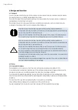
If not otherwise specified in the technical data, the following colour codes apply to the power supply and 
signal connections for components included in Festo Didactic’s learning system for automation and 
technology. 
 

Colour 

Function 


Colour 

Function 


Voltage greater than SELV  
e.g. line voltage of 90 to 400 V AC per conductor 
(grey) 


24 V DC 
(red) 


Neutral conductor 
(grey/blue) 


0 V DC 
(blue) 


Protective conductor 
(green-yellow) 


Safety extra-low voltage, 
signal input/output 
(black) 

 
The specified protection class and safe use can only be assured if laboratory safety cables supplied by Festo 
Didactic are used. 


Damaged laboratory safety cables must be immediately barred from further use 
and removed from the test area. 


1.3


Note to electrical access of facility 

According to EN 60204-1 (VDE 0113-1) part 8.2.8, a supply cable with an additional protective conductor is 
required for the supply of the CP factory installations. Since a leakage current of >10mA can flow depending 
on the configuration, an additional protective conductor with 10mm² is necessary. 
 
Please see also DIN EN 60204-1. 

Summary of Contents for CP Lab

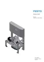
Page 1: ...Festo Didactic CP Factory CP Lab 06 2017 CP Factory CP Lab Manual application module iDrilling...

Page 2: ...training staff must ensure that the trainees observe the safety precautions Festo Didactic accepts no liability for injury or harm to trainees the training company and or any third parties occurring w...

Page 3: ...____________________________________________ 11 4 Design and function_______________________________________________________________________ 12 4 1 Transport___________________________________________...

Page 4: ...____________________________ 31 6 2 Sequence description of the application module drilling _____________________________________ 31 6 3 Setting the application module drilling at HMI ________________...

Page 5: ...afety requirements and safety regulations and whose training has been accordingly documented No damaged or defective devices may be used Damaged devices must be barred from further use and removed fro...

Page 6: ...st be switched off and its mains plug must be removed from the electrical outlet before installation repair maintenance and cleaning work Observe the manual in particular all safety instructions Non o...

Page 7: ...ue Protective conductor green yellow Safety extra low voltage signal input output black The specified protection class and safe use can only be assured if laboratory safety cables supplied by Festo Di...

Page 8: ...gulations are to be observed DIN 58126 and VDE 0100 1 4 3 Dangers due to electric current As soon as maintenance is completed check the function reliability of the safety devices Only trained experts...

Page 9: ...ning operations Activities in the areas of maintenance service and repair are to be carried out by only persons with appropriate technical qualifications 1 6 Obligations of the operating company The o...

Page 10: ...ting up of the system Unlawful constructional modifications on the system Inadequate monitoring of components subject to wear Incorrectly carried out repairs Catastrophes as a result of foreign bodies...

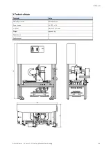
Page 11: ...c CP Factory CP Lab application module drilling 11 3 Technical data Parameter Value Operating pressure 600 kPA 6 bar Power supply 24 V DC 4 5 A L x W x H 382 x 215 x 574 mm Weight approx 5 kg Digital...

Page 12: ...ifts or one fork lift truck Please check the stability of all of the profile connectors by means of an Allen key size 6 The connectors may have come loose during transport due to inevitable vibration...

Page 13: ...iDrilling is designed for Providing a housing lower part with 4 drilled holes During this it is queried whether it is placed correctly without cover The drilling unit will make 2 drilled holes into th...

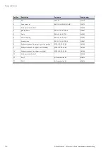
Page 14: ...YSR A 530907 5 Z axis DGSL 10 40 E3 Y3A 543905 6 Z axis clamping DGSL 10 40 E3 Y3A 543905 7 X axis driven DGC 12 120 KF YSR A 530907 8 Workpiece request lower part in correct position SOEZ LLK SE 2 0...

Page 15: ...will be checked The workpiece request 3 checks if there is a front cover on the carrier The workpiece request in the middle 2 checks if there is a back cover on the lower part The left request 1 chec...

Page 16: ...r there must be no back shell on the front shell the position of the front shell must be correct in the goods carrier 3 The drilling machines are switched on Depending on the drill program the X axis...

Page 17: ...nk X axis left VN BG1 KF1 X2 0 I0 0 X axis right VN BG2 KF1 X2 1 I0 1 0 Front cover right orientation VN BG3 KF1 X2 2 I0 2 0 Front cover available VN BG4 KF1 X2 3 I0 3 Z axis top VN BG5 KF1 X2 4 I0 4...

Page 18: ...cation SysLink X axis to left VN MB1 KF1 X4 0 Q0 0 X axis to right VN MB2 KF1 X4 1 Q0 1 Drill 1 via start up current limiter 52Q1 VN QA3 IN KF1 X4 2 Q0 2 Drill 2 via start up current limiter 52Q2 VN Q...

Page 19: ...ment of all connections 5 1 Workstation For starting up the application module iDrilling you need the application module iDrilling a basic module linear shunt bypass for the assembly of the module a c...

Page 20: ...t nuts M5 are put into the front slot of the front cross profile Then two other slot nuts are put into the back slot of the profile Afterwards the slot nuts have to be adjusted to the distance of the...

Page 21: ...le are now connected to the cross profiles but not fastened yet When all screws are placed the application module can still be moved to the position required Please make sure that the workpieces can b...

Page 22: ...is done on the principle of the following sketch The application module is connected from the valve terminal to the on off valve at the conveyor You only have to plug the tube nominal size 4 into the...

Page 23: ...ition Designation 1 fibre optic unit 3x available 165327 SOEG L Q30 P A S 2L 2 Locking screw for clamping adjusting the sensor socket vertically 3 Sensor socket with sensor and light deflection 165360...

Page 24: ...ards each other to the application Align the transmitter and receiver fibre optics Attach the fibre optics to the fibre optic unit You might have to turn the adjusting screw with a small screwdriver u...

Page 25: ...xis cylinder Position Designation 1 X axis on the left 173210 SME 10 KL LED 24 2 X axis on the right 173210 SME 10 KL LED 24 The proximity switches are used for checking the end position of the cylind...

Page 26: ...be queried 2 Move the proximity switch as far as the switching status display LED appears 3 Move the proximity switch into the same direction by a few millimetres as far as the switching status displa...

Page 27: ...Proximity switch Z axis Position Designation 1 Z axis top 173210 SME 10 KL LED 24 2 Z axis bottom 173210 SME 10 KL LED 24 The proximity switches are used for checking the end position of the Z axis Th...

Page 28: ...oximity switch as far as the switching status display LED appears 3 Move the proximity switch into the same direction by a few millimetres as far as the switching status display disappears 4 Move the...

Page 29: ...er 3 One way flow control valves GRLA for X axis cylinder 4 One way flow control valves GRLA for X axis cylinder One way flow control valves are used for regulating the exhaust air volume of double ac...

Page 30: ...until the required piston speed has been reached Documents Data sheets One way flow control valve 193138 5 5 Visual inspection Visual inspection must always be carried out before starting up Before s...

Page 31: ...regulations which have to be observed strictly If you don t observe the rules there might occur faults in the process Dangers to your physical health can also not be excluded It is strongly recommend...

Page 32: ...Operation 32 Festo Didactic CP Factory CP Lab application module drilling Automatic Mode sequence step 1 6...

Page 33: ...Operation Festo Didactic CP Factory CP Lab application module drilling 33 Automatic Mode sequence step 7 12...

Page 34: ...Operation 34 Festo Didactic CP Factory CP Lab application module drilling Automatic Mode sequence step 14...

Page 35: ...application module drilling 35 6 3 Setting the application module drilling at HMI To set the application module the application module must be set to setup mode 1 On the Start screen click Setup Chang...

Page 36: ...VN_BG6 indicator lights up green when Z axis is down Down Move the Z axis down actuator VN_MB6 is activated lights up blue when active 3 Activate drill 1 Drill 1 Switch on drill 1 actuator VN_MB3 is...

Page 37: ...ication module drilling 37 6 4 Transitions of the application module The transitions are located in the Parameters submenu The transitions can be displayed or changed here The transitions are used in...

Page 38: ...ill both sides as viewed in the transport direction Limitation No limit of the value in the transition table 2 Not used 3 Not used 4 Not used MES Operation Parameter Number Description Nr Name 120 Dri...

Page 39: ...Operation Festo Didactic CP Factory CP Lab application module drilling 39 Festo Didactic SE Rechbergstra e 3 73770 Denkendorf Germany Internet www festo didactic com E mail did de festo com...

Reviews: