Connection Buffer/Feeder
Bushing
Pin
Signal
O/1
24 V DC/Box ready
–
Reference voltage for sensors (switched off in Stop status)
–
Operating readiness status
–
Control for transport device (e.g. conveyor)
O/2
Feeder
Control of the small parts conveyor
(e.g. upstream conveyor pot)
3
GND
Reference voltage for sensors
I/4
Buffer
Buffer zone sensor 1
5
Do not connect
Tab. 5: Connection Buffer/Feeder
Connection Ethernet
Bushing
1)
Pin
Signal
1
TD+
Transmitted data +
2
RD+
Received data +
3
TD–
Transmitted data –
4
RD–
Received data –
Metal covering
Shielding (Shield)
1) M12, D-coded
Tab. 6: Connection Ethernet
Connection Encoder
Bushing
Pin
Signal
Interface for rotary pulse encoder as per RS 485 specification
1
A+
2
n.c.
3
B+
4
A–
5
B–
6
5 V power supply
1)
7
GND
8
n.c.
1) Maximum load 180 mA
Tab. 7: Connection Encoder
4.2
Function
The product enables the optical (contactless) positioning and quality inspection
of conveyed parts and it precisely controls the actuator technology for sorting
the inspected parts and parts assigned to the result groups (tracking, ejection of
parts, etc.).
5
Assembly
CAUTION
Glare and eye irritation.
With regard to the blue light hazard, the product exceeds the limit values of the
Freie Gruppe according to DIN EN 62471:2009-03. Therefore, an assignment to
risk group 1 applies for the blue light hazard. Looking at the light source for a long
or prolonged period can dazzle your eyes and cause irritation.
Take measures to prevent eye exposure:
• Do not remove any housing parts.
• Only mount or remove the prism support when the power supply is switched
off.
• Mount the product only in its original state with closed, intact housing.
• Only assemble or disassemble the product when it is switched off.
• Mount the product in such a way that direct view into the light beam is not
possible.
• Also take measures to ensure that if the light beam is reflected off mirrored
or reflective objects, it does not pose a hazard, for example, by providing
screening.
• Do not stare directly into the light beam and do not direct the beam into the
eyes of other people.
Ordinary light sources are divergent, i.e. the illuminated area becomes larger as
the distance from the light source increases. As a result, the risk of eye injury
decreases as the distance from the light source increases. However, because the
product uses parallel light, the risk of eye injury is not reduced as the distance
increases; this applies to both looking directly at the beam and looking into the
beam via a reflective surface.
Installation location
Please note the following ambient conditions in particular:
–
Low vibration installation
–
Stable mechanical mounting
–
Clean ambient air: oil-free, no paint mist, no sanding dust
–
Screening of external light influences, external heat and extreme magnetic
fields (e.g. due to induction furnaces).
–
Mounting as cool and vertical as possible
This will ensure optimal inspection results and a long service life for the device.
Transporting device
In order to ensure a reliable and reproducible test result, the transporting device
used should fulfill the following requirements:
–
Use a high-grade transporting system which conveys the parts at a constant
speed.
–
Ensure that the parts are stable, e.g. by using mechanical devices.
–
Ensure smooth transfer of parts from the small parts conveyor to the trans-
porting device and that the transporting device is mechanically decoupled from
the small parts conveyor.
–
Also use mechanical devices to transfer parts securely from the transporting
device to the buffer zone (e.g. drop pipe, slide, chute) of the downstream
machine to prevent changes in the orientation of parts.
Mounting
A mounting profile with a dovetail guide is installed on the side of the product.
If the product is mounted from the other side, the mounting profile must be
dismantled and fixed on the opposite side.
CAUTION
Damage to components.
• Modify the product only in a clean environment.
• Use suitable screws. The screw-in depth in the device is limited to a maximum
of 6 mm.
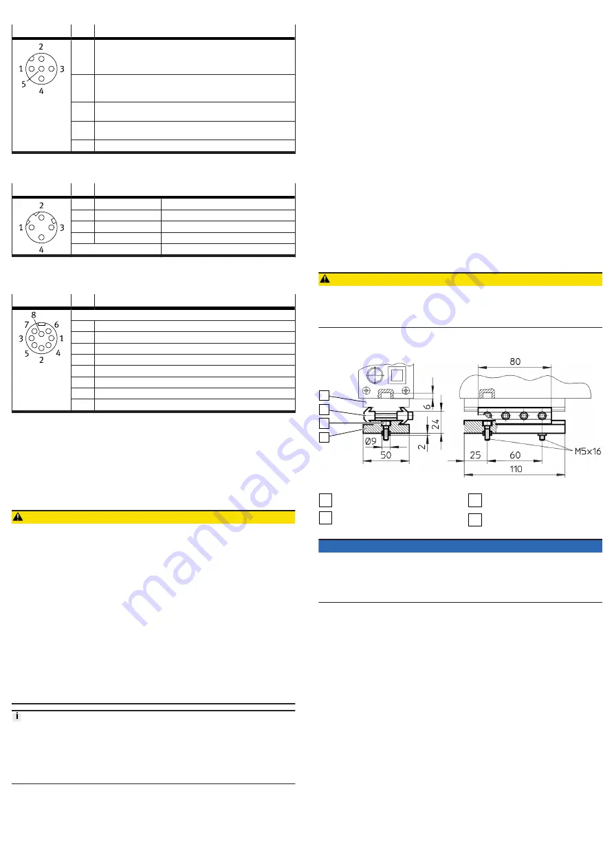
The connection kit HMSV-12 is available as an accessory
2
1
3
4
Fig. 3: Mounting with connection kit HMSV-12
1
Mounting profile of the CHB-CN
2
Clamping elements with 4 M5x45
socket head screws
3
2 M5x16 socket head screws with
centring sleeves
4
Adapter plate
NOTICE
In order that a reliable test result can be achieved, the glass surfaces on the prism
supports must not be scratched or dirty:
• Mount the product so that passing parts do not touch the glass surfaces.
• Ensure that the parts are stable, e.g. with mechanical devices.
• Clean the glass surfaces as required.
When mounting the product above the transport device, note the following:
–
Attach the product to the transport device to form a stable unit.
–
Keep the camera's field of view clear.
–
Do not cover the optical channel with the transport device.
The product has excellent imaging properties over the entire working space. The
contrast of the image is optimised for very fine details on the sensor side.
–
To achieve maximum contrast for small details, mount the product so the
objects pass as close as possible to the prism support on the sensor side. This
is the side with the Start/Stop illuminated pushbutton.


