background image


0101-9031-0 


Genius II  

Quick Start Guide 


                Revision B, December 2015


Temescal, a division of Ferrotec (USA) Corporation        

4569-C Las Positas Road, Livermore, CA  94551 

Tel: 1-800-522-1215; Fax: 925-449-4096 


Ferrotec GmbH


Seerosenstr. 1, 72669 Unterensingen,  

AG Stuttgart, Germany 

Tel.: +49 7022 9270 0 

        +49 7022 9270 10 


Summary of Contents for Genius II

Page 1: ...n B December 2015 Temescal a division of Ferrotec USA Corporation 4569 C Las Positas Road Livermore CA 94551 Tel 1 800 522 1215 Fax 925 449 4096 Ferrotec GmbH Seerosenstr 1 72669 Unterensingen AG Stuttgart Germany Tel 49 7022 9270 0 49 7022 9270 10 ...

Page 2: ...By A First released version of document Applies to all Genius II units sold after November 2015 Dec 2015 IA B Correct internal cross references on pp 7 and 8 Also deleted former and redundant Figure 2 Applies to all Genius II units sold after November 2015 Dec 2015 IA 2015 Ferrotec USA Corp ...

Page 3: ...igure 11 Configuration Main Screen After User Configures All Control Modules as Remote I O 11 Figure 12 Configuration E Beam Screen After Initial Boot Up 11 Figure 13 Config Turret Screen at Initial Boot Up 12 Figure 14 Config Turret Screen After User Alters Rotation Seek Speed and Index Speed 13 Figure 15 Config Turret Screen After Turret Configuration Procedure is Completed 14 Figure 16 Config S...

Page 4: ...int delivery of product and manual is definitive We reserve the right to make technical changes without prior notice All previous revisions of this manual then lose their validity The Genius II controller is part of a group of devices for the operation of an electron beam evaporator installed in a vacuum chamber This group of devices consists of 1 a high voltage power supply HVPS 2 the Genius II c...

Page 5: ...he material media manufacturers must be observed Copyright No part of this publication may be reproduced transmitted sold or disclosed without prior permission Damages will be claimed for violations All rights reserved The controller and this manual are protected by copyright Copying of the devices will be prosecuted All rights to this manual are reserved including reproduction in any conceivable ...

Page 6: ...ies These symbols mark the sites of protective conductor connections Environment sign indicates actions to protect the environment This symbol reminds personnel to wear personal safety equipment including safety glasses This instruction handbook is an integral part of the deposition controller and must be kept readily at hand for the operating personnel at all times The safety instructions contain...

Page 7: ... serial number of the deposition controller The manufacturer guarantees warranty of the product of 12 months to be free on defects caused by material failure or failures caused by the manufacturing process If a fault occurs during this time period the manufacturer guarantees free of charge repair in regards of parts and labor time Warranty exclusions Damages caused by improper or not intended use ...

Page 8: ...01010 9031 0 Rev B vi Genius II Quick Start Guide ...

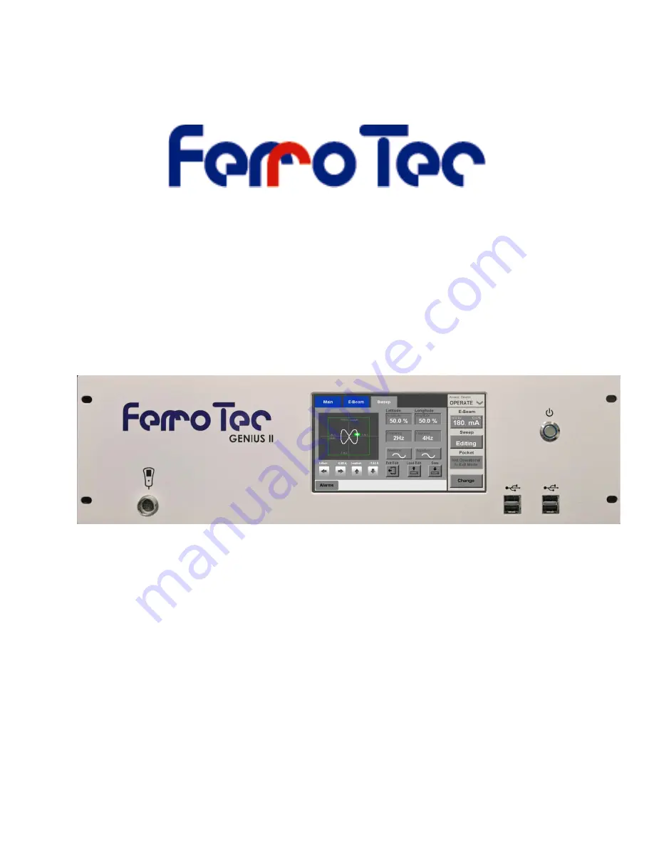
Page 9: ...n a standard 19 inch rack Magnet connection cable PN 1 9500003 Input power cable PN 1 9500024 Grounding cable PN 1 9500001 1 2 Basic Hardware Installation Step Action 1 Using the mounting hardware supplied install the Genius II controller in a standard 19 inch rack 2 Plug the connector on the end of the remote controller s cable into the port indicated in Figure 1 Figure 1 Genius II Front Panel Sh...

Page 10: ... and lateral axes 1 3 2 Basic Cabling Procedure Figure 2 shows the connectors on the Genius II rear panel The following procedure describes the basic cabling connections to be made to via those connectors and Figure 3 illustrates those cabling connections For additional details about connections to be made via rear panel connector X110 see Figure 4 and Table 1 For details about connections to be m...

Page 11: ...r end of this cable to the male 15 pin connector on the turret drive unit mounted beneath the source tray see Figure 3 10 Connect one end of the grounding cable PN 1 9500001 to the grounding stud on the Genius II rear panel see Figure 3 11 Connect the other end of the grounding cable to the system s central grounding point 12 Connect the required water vacuum and vacuum chamber door interlock swit...

Page 12: ...1 3 Making Cable Connections 1 3 2 Basic Cabling Procedure Genius II Quick Start Guide 0101 9031 0 Rev B 4 Figure 3 Genius II Cabling Diagram ...

Page 13: ...1 3 2 Basic Cabling Procedure 1 3 Making Cable Connections 0101 9031 0 Rev B 5 Genius II Quick Start Guide ...

Page 14: ...e provided with the deposition controller connect Genius II rear panel connector X111 to the BNC connector on the deposition controller rear panel which outputs the emission current request If you are connecting the Genius II to either an Inficon XTC 3S or an XTC 3M connect the BNC connector to the XTC s SOURCE 1 connector If a BNC cable was not supplied with your deposition controller use a stand...

Page 15: ...n A6 to a user determined output from the higher level controller Figure 5 shows how this input could be supplied by an XTC 3M deposition controller using its IN LAYER output A7 Output K1 Relay contact with Pin B7 default function HV ON status HV ON 1 A8 Output K2 Relay contact with Pin B7 default function Genius II ERROR indicator ERROR 1 B1 Ground reference for Pin A1 jumper to Pin B5 B2 Ground ...

Page 16: ...ions between the higher level controller and rear panel connector X119 This wiring can follow either of two configurations as shown in Figures 6 and 7 Table 2 provides functional descriptions of the I Os exchanged via connector X119 Figure 6 Connections to Rear Panel Connector X119 Configuration 1 Figure 7 Connections to Rear Panel Connector X119 Configuration 2 ...

Page 17: ...t K3 Relay contact with B5 function POS 1 BCD bit 1 B4 Output K4 Relay contact with B5 function POS 2 BCD bit 2 B5 COM OUT Function Either 0 V reference for Outputs K1 K4 if jumpered to Pin B8 or 1 5 A control voltage for the same outputs if jumpered to Pin A8 B6 Output T1 Transistorized output not implemented on Genius II B7 Output T2 Transistorized output not implemented on Genius II B8 Internal...

Page 18: ...l Module Control Modules for Remote Control Step Action 1 When the Genius II is first booted up the main controller screen displays the Start screen see Figure 9 To put the unit into Configuration Mode touch this screen s Configuration button The unit will then display the Configuration Main screen see Figure 10 Figure 9 Genius II Start Screen Figure 10 Config Main Screen After Initial Boot Up Not...

Page 19: ...he EBeam Control Module Step Action 1 Touch the Menu Bar s E Beam button to display the Config E Beam screen see Figure 12 Figure 12 Configuration E Beam Screen After Initial Boot Up 2 Select the desired power supply if it is not already selected To do so touch the Carrera Type button to toggle between the four power supply options 3 Leave EXTERNAL selected opposite Emis Control 4 If desired you c...

Page 20: ...time exit Configuration Mode to save the configuration see section 1 5 5 for detailed instructions If not proceed to section 1 5 3 1 5 3 Configuring the Turret Control Module Overview of the Config Turret Screen Figure 13 shows the Configuration Turret screen as it appears when the Genius II is first booted up Figure 13 Config Turret Screen at Initial Boot Up The features on this screen enable the...

Page 21: ...display a keypad popup and use it to enter the desired value b Touch the keypad s Enter button to close it and set the new jog speed value The value you entered will then appear on the Seek Speed button NOTE The drive motor s rotation speed is four times that of the turret 4 Select the drive motor s index speed To do so a Touch the Index Speed button to display a keypad popup and use it to enter t...

Page 22: ...ure is now completed If you have made all the configuration changes you wish to make at this time exit Configuration Mode to save the configuration see section 1 5 5 for detailed instructions If not proceed to section 1 5 4 1 5 4 Configuring the Sweep Control Module Overview of the Config Sweep Screen The Config Sweep screen enables the user to set the limits for the beam position interlocks Figur...

Page 23: ... current position Coil Drive Polarity buttons which enable the user to reverse the polarity of the sweep drive coils if that is required Sweep Module Configuration Procedure Step Action 1 Touch the Menu Bar s Sweep screen to display the Config Sweep screen 2 Open the shutter so that the pocket in evaporation position is visible through the viewport 3 Switch on the beam at a power level 3 5 at whic...

Page 24: ... Control Module Genius II Quick Start Guide 0101 9031 0 Rev B 16 Figure 18 Remote Controller in Config Mode with Menu 1 Selected and Beam on at 5 6 Touch the remote controller s Pos Adjust button The remote controller s screen will then appear as shown in Figure 19 ...

Page 25: ... beam to the desired position for the Latitude beam position interlock limit 8 Press the remote controller s Menu button to select Menu 2 which is shown in Figure 20 9 With Menu 2 displayed press the Set Lat button to set the Latitude beam position limit at this position The screen will then appear as shown in Figure 20 with a white dashed line indicating the limit you have just set With Pos Adjus...

Page 26: ...position desired for the Latitude beam position limit 11 When the beam is at the position desired for the latitude limit press the Set Lat button 12 Use the joystick to move the beam to the position desired for the Longitude beam position limit 13 When the beam is at the position desired for the longitude limit press the Set Long button 14 Use the joystick to move the beam to the position desired ...

Page 27: ...n parameters However if you wish to assign specific materials to specific pockets follow the instructions provided in section 3 8 of the Genius II User Manual before exiting from Configuration mode Likewise if you wish to enable the LogIn manager and assign user passcodes and permissions follow the instructions provided in section 3 7 of the Genius II User Manual before proceeding to section 1 5 5...

Page 28: ...eted Auxiliary Menu Displayed 2 Touch the Auxiliary Menu s Change Mode button to display the mode select popup which is shown in Figure 23 Figure 23 User Exiting Configuration Mode Mode Select Popup Displayed 3 3 To exit from Configuration Mode and save your changes touch any active button on this popup The Genius II will then enter the selected mode The unit is now ready for normal system operati...

Reviews: