Ferroli SKY C B Instructions For Use, Installation And Maintenance Download Page 6

SKY C B

6

IT

cod. 3541C702  -  Rev. 01 - 06/2014

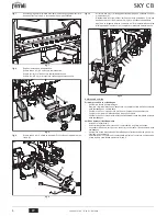
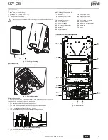
5.2 Schemi idraulici

fig. 15 - Circuito idraulico

5.3 Tabella dati tecnici

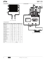
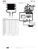
5.4 Schema elettrico

fig. 16

Dato

Unità

SKY C 11 B

SKY C 14 B

Portata termica max

kW

21.7

26.9

(Q)

Portata termica min

kW

8.3

10.3

(Q)

Potenza Termica max

kW

19.2

23.9

Potenza Termica min

kW

7.1

8.8

Rendimento Pmax

%

88.5

88.7

Ugelli bruciatore G20

n° x Ø

10 x 1.25

12 x 1.25

Pressione gas alimentazione G20

mbar

20.0

20.0

Portata gas max G20

m

3

/h

2.30

2.85

Portata gas min G20

m

3

/h

0.88

1.10

Ugelli bruciatore G30

n° x Ø

10 x 0.77

12 x 0.77

Pressione gas alimentazione G30

mbar

29.0

29.0

Portata gas max G30

kg/h

1.70

2.11

Portata gas min G30

kg/h

0.65

0.80

Ugelli bruciatore G31

n° x Ø

10 x 0.77

12 x 0.77

Pressione gas alimentazione G31

mbar

37

37

Portata gas max G31

kg/h

1.70

2.11

Portata gas min G31

kg/h

0.65

0.80

Pressione max esercizio

bar

10

10

(PMS)

Pressione min esercizio

bar

0.20

0.20

Portata sanitaria 

'

t 25°C

l/min

11.0

14.0

Portata sanitaria 

'

t 50°C

l/min

5.5

6.8

(D)

Grado protezione

IP

X5D

X5D

Peso a vuoto

kg

11

12

Tipo di apparecchio

B

11BS

PIN CE

0461CL0984

8

9

358

49

42

82

188

Marking

7 8 9 10 11 12 13 14 15 16

6

5

4

3

2

1

4 3 2 1

126

49

3 2 1

DISPLAY

44

359

3 2 1

358

1

2

_+

372

ON/OFF

42

83

Summary of Contents for SKY C B

Page 1: ...95 11 CB 14 CB A 295 335 Modello 7 9 8 a4 110 130 B 210 250 IT ISTRUZIONE PER L USO L INSTALLAZIONE E LA MANUTENZIONE EN INSTRUCTIONS FOR USE INSTALLATION AND MAINTENANCE FR INSTRUCTIONS D UTILISATION...

Page 2: ...ccensione e spegnimento Verifiche e operazioni preliminari 1 Accertarsi che i rubinetti dell acqua calda siano chiusi 2 Aprire il rubinetto di alimentazione del gas allo scaldabagno situato sull allac...

Page 3: ...tare le nor me vigenti B Lo scaldabagno dotato di un dispositivo di sicurezza termostato fumi che blocca il funzionamento dell apparecchio in caso di cattivo tiraggio o ostruzione della canna fumaria...

Page 4: ...la targhetta dei dati tecnici per comprovare l avvenuta trasformazione fig 10 4 2 Messa in servizio Prima di accendere lo scaldabagno Verificare la tenuta dell impianto gas Riempire l impianto idrauli...

Page 5: ...da ostacoli e non presentare perdite Il bruciatore e lo scambiatore devono essere puliti ed esenti da incrostazioni Per l eventuale pulizia non usare prodotti chimici o spazzole di acciaio Gli elettro...

Page 6: ...ruciatore G30 n x 10 x 0 77 12 x 0 77 Pressione gas alimentazione G30 mbar 29 0 29 0 Portata gas max G30 kg h 1 70 2 11 Portata gas min G30 kg h 0 65 0 80 Ugelli bruciatore G31 n x 10 x 0 77 12 x 0 77...

Page 7: ...calcare inadegua tra amen dell acqua e o tra amen disincrostan erroneamente e e ua corrosioni causate da condensa o aggressivit d acqua gelo corren vagan e o e e dannosi di scariche atmosferiche manca...

Page 8: ...shutdown Preliminary operations and checks 1 Make sure the hot water taps are closed 2 Open the water heater gas supply cock located on its gas connection 3 Make sure the 1 5 V batteries are properly...

Page 9: ...on of the flues and connection pipe B The water heater has a safety device fume thermostat that stops unit opera tion in case of poor draught or obstruction of the flue This device must never be tampe...

Page 10: ...sticker contained in the conversion kit near the data plate as proof of the conversion fig 10 4 2 Commissioning Before lighting the water heater Check the tightness of the gas system Fill the hydraul...

Page 11: ...ree of any obstacles and leaks The burner and exchanger must be clean and free of deposits For possible clean ing do not use chemical products or wire brushes The electrodes must be free of deposits a...

Page 12: ...Burner nozzles G30 no x 10 x 0 77 12 x 0 77 Gas supply pressure G30 mbar 29 0 29 0 Max gas delivery G30 kg h 1 70 2 11 Min gas delivery G30 kg h 0 65 0 80 Burner nozzles G31 no x 10 x 0 77 12 x 0 77 G...

Page 13: ...S par pr l vement d ECS l afficheur visualise la temp rature actuelle de l eau sur la sortie ECS 2 3 Allumage et extinction V rifications et op rations pr liminaires 1 S assurer que les robinets de l...

Page 14: ...e des conduits de fum e et du tuyau de raccordement B Le chauffe eau est dot d un dispositif de s curit thermostat des fum es qui bloque l appareil en cas de tirage incorrect ou si le conduit est colm...

Page 15: ...la plaquette des donn es techniques afin de signaler la transfor mation effectu e fig 10 4 2 Mise en service Op rations effectuer avant d allumer le chauffe eau V rifier l tanch it de l installation...

Page 16: ...cle et ne pr senter aucune fuite Le br leur et l changeur doivent tre propres et d tartr s Pour le nettoyage ne pas utiliser de produits chimiques ni de brosses en acier Les lectrodes ne doivent pr se...

Page 17: ...88 01 10 Gicleurs br leur G30 nbre x 10 x 0 77 12 x 0 77 Pression d alimentation gaz G30 mbar 29 0 29 0 D bit gaz maxi G30 kg h 1 70 2 11 D bit gaz mini G30 kg h 0 65 0 80 Gicleurs br leur G31 nbre x...

Page 18: ...G sterge sembollerinin anlamlar S cak s hhi su al nmas ile olu an s hhi su talebi esnas nda g sterge akt el s cak s hhi su k s cakl n g r nt ler 2 3 A ma ve kapatma lk kontroller ve i lemler 1 S cak s...

Page 19: ...kanmas halinde cihaz n al mas n engelleyen bir emniyet cihaz duman termostat ile donat lm t r Bu cihaz asla kurcalanmamal veya devre d b rak lmamal d r 4 SERVIS VE BAK M A klanan t m ayarlama servise...

Page 20: ...eki etiketi teknik veriler etiketinin yan na yap t r n ek 10 4 2 Servise alma Su s t c s n yakmadan nce Gaz sisteminin s zd rmazl n kontrol ediniz Su sistemini doldurunuz ve su s t c s ile sistem i er...

Page 21: ...man kanallar nda ve terminalinde herhangi bir t kan kl k ve ka ak olmamal d r Br l r ve e anj r temiz ve tortusuz olmal d r Temizlik i lemlerinde kimyasal r nler veya elik f r alar kullanmay n z Elekt...

Page 22: ...10 Br l r u lar G30 n x 10 x 0 77 12 x 0 77 Gaz besleme bas nc G30 mbar 29 0 29 0 Maks gaz kapasitesi G30 kg sa 1 70 2 11 Min gaz kapasitesi G30 kg sa 0 65 0 80 Br l r u lar G31 n x 10 x 0 77 12 x 0 7...

Page 23: ...s k Voltaj 2004 108 Elektromanyetik Uygunluk Y netmeligi Baskan ve yasal temsilci Dep Dante Ferroli TR Declaration of conformity Manufacturer FERROLI S p A Address Via Ritonda 78 a 37047 San Bonifaci...

Page 24: ...FERROLI S p A Via Ritonda 78 a 37047 San Bonifacio Verona ITALY www ferroli it...

Reviews: