Ferroli RMA2 HE VB 19.1 Installation And Operation Manual Download Page 25

25

HYDRAULIC CONNECTIONS

General rules

A mesh filter (hole Ø<0,5mm for plates heat exchanger) must be installed on the unit’s water inlet otherwise warranty is immediately for-

feited .  The filter performs the function of blocking any foreign matter in the system’s plumbing circuit (shavings, machining debris, etc .) 

limiting or avoiding possible problems of fouling (that decreases the heat exchange coefficient), erosion, and clogging

The clogging and fouling of the exchanger can lead to a reduction of the water flow rate and . In the case that the exchanger works as 

evaporator- of the evaporation temperature: these 2 factors can cause the icing of the exchanger

The icing event leads to the bursting of the exchanger, the inlet of water into the refrigerant circuit and so the necessity of a replacement of 

the main components (compressors, filters, expansion valves, . Etc .)  and an accurate washing of components as refrigerant pipes, coils, 

etc ., practically the rebuilding nearly complete of the refrigerant circuit .
The filter must be maintained clean: this is so necessary verify the cleanness after the unit installation and checking periodically the state .

Protection devices

Standard supply includes a differential pressure switch situated between the water inlet and outlet of the heat exchanger to avoid freezing if 

the water flow stops for any reason.

• Standard supply includes an antifreeze heater placed between the external thermal insulation and the shell of the exchanger and controlled 

by the main electronic controller of the unit in order to protect the evaporator full of water (but not the pipes) from the winter icing when the 

unit is in stand-by mode. The exchanger is protected down to an outdoor air temperature of -20°C.

NOTE the antifreeze protection only worlk if the unit is electrically connected the standby period . 

It is recommended to install a water paddle flow switch at

 the water inlet of the unit: the water paddle flow switch has to be electrically wired 

in series with the differential pressure switch.

It is mandatory to calibrate the trip out of the water paddle flow switch at a water flow rate value higher than the minimum water flow rate 

admissible for the exchanger (re. section Pressure Drop).

Tips for a successful installation

For a correct design and installation of the hydraulic plant comply the local laws governing safety matters and sound… 

The following information is suggestion for a correct installation of the unit:

• Before connecting the unit to the system wash adequately the pipes using clean water, filling and emptying and cleaning the filters.

Only after that proceed connecting the unit to the system; this operation is crucial to ensure proper start-up without the need to have repeated 

stops to clean the filter, with the possible risk of damage to heat exchangers and other components.

• Check by qualified personn

el the quality of the water or of the mixture used; avoid the presence of inorganic salts, biological load (seaweeds, 

etc.) suspended solids, dissolved oxygen and the pH. Water with inadequate characteristics can cause a pressure drop increase due to a 

rapid fouling of the filter, energy efficiency decrease and corrosive symptom increase that can damage the unit.

• The pipes must have the least possible number of bends to minimize load losses and must be adequately supported in order to prevent the 

connections of the unit from being excessively stressed.

• Install on-off valves near components that need to be serviced to isolate them when maintenance work needs to be done and to allow them 

to be replaced without having to discharge the system.

• Before isolating the pipes and charging the system, carry out preliminary inspections to make sure that there are no leaks.

• Isolate all the chilled water pipes to prevent condensation from forming along the pipes themselves. Make sure that the material used is the 

steam barrier type, failing this, cover the insulation with an appropriate protection. Also make sure that the air venting valves can be accessed 

through the insulation.

• Do not forget to install or at least allow for the installation of pressure and temperature reading instruments on the inlet and outlet parts of 

the hydraulic circuit. These instruments will allow you to monitor the operation of the system.

• The circuit can be kept under pressure by means of an expansion tank and a pressure reducer. A plant filling unit can also be used in order 

to automatically charge the system and keep it at the desired pressure if it drops below a certain pressure value. Install manual or automatic 

values in the highest point of the system to eliminate air from the circuit.

Fit manual or automatic valves at the highest point in the circuit in order to vent air from the circuit.

• the water connections are Victaulic-type joints for hooking up to the unit.

The joints allow the pipes to expand due to changes in temperature and in addition the elastomer gasket and the specified play help insulate 

and absorb noise and vibration.

• If vibrations dampers are installed under the unit, it is recommended to use flexible couplings before and after the water circulation pump 

and near the unit.

• Install on the outlet of the unit a suitable valve able to regulate the water flow.

• Avoid that the weight of the connection pipes pushes on the hydraulic connections of the unit using approved supports.

Check that plant components are suitable to bear the maximum static pressure (it depends on the height of the building).

VP

E

V

SUW

SIW

T

U

O

P

S

N

I

PD

P

S

V

RM

RA

ATTENTION

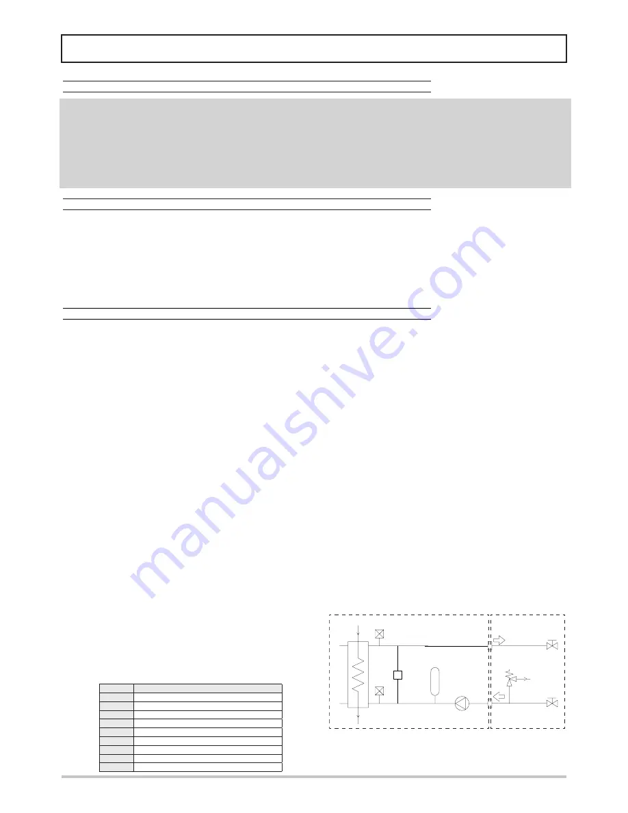
For units in VP version equipped with expansion vessel is required to 

install a safety valve (SET = 3 bar) on the hydraulic circuit. If the unit is 

disconnected from the rest of the hydraulic system with shut-off valve or 

other equivalent device (eg during maintenance), check that the safety 

valve is always connected with the expansion vessel. See diagram:

VP unit version

operation by the 

installer

ITEM

DESCRIPTION

P

PUMP

PD

DIFFERENTIAL PRESSURE WATER

RA

SUCTION BALL VALVE

RM

DISCHARGE BALL VALVE

SIW

PROBE WATER INLET

SP

HEAT EXCHANGER

SUW

PROBE WATER OUTLET

VS

SAFETY VALVE

VE

EXPANSION TANK

Summary of Contents for RMA2 HE VB 19.1

Page 1: ...RMA2 HE AIR WATER CHILLERS AND HEAT PUMPS FOR OUTDOOR INSTALLATION INSTALLATION AND OPERATION MANUAL R E F R I G E R A N T G A S E C O FRIEND L Y E U ROVEN T E F F I C I E N C Y E N E R G Y C LA S S...

Page 2: ...of experiences and of particular research studies and has been made with top quality materials and advanced technologies The CE mark guarantees that the products satisfy all the applicable European Di...

Page 3: ...RKING HEAD 20 DIMENSIONAL AND PHYSICAL DATA 22 Overall dimensions 22 Minimum operating area 22 Weights 23 RECEPTION AND POSITIONING 24 Receiving 24 Positioning 24 HYDRAULIC CONNECTIONS 25 General rule...

Page 4: ...nformation in this manual which describes the procedures required to correctly install and use the unit Strictly comply with the instructions in this manual and conform to the current safety standards...

Page 5: ...ce noise emissions in such operating conditions The low noise acoustic setting up AS is obtained starting from the base setting up AB reducing the rotational speed of the fans and mounting sound jacke...

Page 6: ...resent in the circuit high and low pressure switches in order to assure the compressor to operate inside the permitted limits 4 way reverse cycle valve 6 to allow operating mode change reversing the r...

Page 7: ...pump operating hours recording serial communication through Modbus protocol remote stand by remote cooling heating general alarm digital output Versions Each model can be supplied in three different v...

Page 8: ...ctivated together with the antifreeze electrical heater of the plate heat exchanger it has the task to keep the water in the buffer tank at a temperature high enough to avoid ice generation during win...

Page 9: ...ates as an integration of the protecion offered by the differential pressure switch standard Coil protection grille Protects the external surface of the finned coil Coils protection kit for transport...

Page 10: ...imum rotational speed 900 900 900 900 900 900 rpm Total installed power 0 6 0 6 0 6 1 8 1 8 1 8 kW Plant side hydraulic circuit Expansion vessel volume VP VA 10 10 10 10 10 10 l Tank volume VA 85 85 8...

Page 11: ...ithout options and accessories IP Heating A2W45 source air in 2 C d b 1 C w b plant water in 40 C out 45 C Heating capacity 17 5 19 5 22 7 27 5 31 9 36 2 kW Power input 6 12 6 70 7 78 9 62 11 1 12 7 k...

Page 12: ...units without options and accessories IP Heating A2W45 source air in 2 C d b 1 C w b plant water in 40 C out 45 C Heating capacity 16 5 18 5 21 6 26 1 30 2 34 3 kW Power input 5 87 6 43 7 46 9 22 10...

Page 13: ...to the section limits The reference nominal condition is A35W7 source air in 35 C d b plant water in 12 C out 7 C Outlet air temperature C D B A 20 C B 25 C C 30 C D 35 C E 40 C F 45 C G 50 C Outlet...

Page 14: ...5 C Heating capacity Total power input Outlet water temperature C Outlet water temperature C A G B F C E D D E C F B G A HEATING performances The standard performances refer to a 5 C temperature diffe...

Page 15: ...ower input 0 935 0 923 0 910 0 888 0 865 0 838 0 810 CCQA Water flow rate 1 072 1 071 1 070 1 069 1 069 1 068 1 067 CCDP Pressure drop 1 160 1 175 1 190 1 200 1 210 1 255 1 300 Percentage Of glycol in...

Page 16: ...field on reflecting surface directional factor equal to 2 The sound power level is measured according to ISO 3744 standard The sound pressure level is calculated according to ISO 3744 and is referred...

Page 17: ...0 1 20 4 10 4 10 4 10 A F L I Maximum total power input 0 60 0 60 0 60 1 80 1 80 1 80 kW L R A Start current 5 0 5 0 5 0 15 0 15 0 15 0 A Power supply 400 3 50 400 3 50 400 3 50 400 3 50 400 3 50 400...

Page 18: ...essory With fans modulating control options and pressure transdu cer accessory Or other antifreeze solutions For these applications requires the use of brine or other antifreeze solutions The table be...

Page 19: ...te Upper limit value Q 8500 10000 11500 12500 140000 14000 l h The graphs are referred to units operating with water at the temperature of 10 C density 1000 kg m 3 10 20 30 40 50 60 70 80 90 100 110 1...

Page 20: ...limit value Q 2500 3000 3500 4000 4500 5250 l h Q Water flow rate Upper limit value Q 4750 7800 8500 8900 kPa The graphs are referred to units operating with water at the temperature of 10 C density 1...

Page 21: ...00 5250 l h Q Water flow rate Upper limit value Q 4750 9500 kPa 0 10 20 30 40 50 60 70 80 90 100 110 120 130 140 150 160 170 180 190 200 210 220 230 240 250 260 270 280 2000 3000 4000 5000 6000 7000 8...

Page 22: ...d accessibility and facilitate maintenance and control operations A 400 mm B 600 mm C 200 mm Plant return Plant flow Frame 1 2 Model 19 1 22 1 26 1 30 1 35 1 40 1 1 1 1 4 F 1 1 4 F 1 1 4 F 1 1 4 F 1 1...

Page 23: ...ping module Standard pump 9 9 9 9 11 11 kg High head pump 12 12 12 12 13 13 kg Modulating pump 12 12 12 14 16 16 kg Tank and standard pump 31 31 31 31 33 33 kg Tank and high head pump 34 34 34 34 35 3...

Page 24: ...o avoid damages to the unit Prevent the unit or parts of it from falling down Storing The units must be stored in a dry place repaired from sun rain sand or wind Do not stack the units Maximum tempera...

Page 25: ...oad seaweeds etc suspended solids dissolved oxygen and the pH Water with inadequate characteristics can cause a pressure drop increase due to a rapid fouling of the filter energy efficiency decrease a...

Page 26: ...r in order to prevent freezing that would seriously jeopardize the operation of the unit Free Chlorine 0 5 ppm Fe3 0 5 ppm Mn 0 05 ppm CO2 50 ppm H2S 50 ppb Temperature 65 C Oxygen content 0 1 ppm To...

Page 27: ...orce The electrical heaters must be connected to a single phase power supply if the unit power supply is single phase or to a three phase power supply if the unit power supply is three phase Upstream...

Page 28: ...or more details refers to section monitoring basic system LEVEL 1 Device Low pressure automatic switch Trip out barg 4 bar IR IP unit in cooling mode 2 bar BR BP IP unit in heating mode Trip in barg 6...

Page 29: ...SL probe liquid STAE Outside air sensor SUW Water outlet probe TPL Liquid pressure transducer VE fan VT thermostatic valve IP unit BE VE CP SL VT FD PP4 S3 S4 SC PA PP3 TPL PB PP1 PP5 PD SUW SIW VES V...

Page 30: ...ed on the unit To each button are associated a direct function indicated on the button itself and activated pressing the button an associated function indicated on the front of the instrument at the c...

Page 31: ...ns Amber Active load Safety time in progress Pump Amber Active load Safety time in progress Display Normally are shown the setting temperature that is the water inlet temperature in tenths of Celsius...

Page 32: ...point heating COOL Display real set point cooling Hr CP01 Display compressor operating hours PU01 Display pump operating hours Programming Press ESC SET buttons at the same time combined functioni ESC...

Page 33: ...freeze heater relay 2 A resistive 250 Vac RAG RE1 Tank antifreeze heater Integrative heater 1st step DO5 P Pump 500mA 12Vdc voltage output for control of relay K1 4 A resistive 250 Vac AO2 RE2 Integra...

Page 34: ...the Alarm digital output is disabled The deactivation of the alarm does not affect the alarm in progress Number of events per hour For some alarms the number of events per hour is recorded if in the...

Page 35: ...ing valve The alarm is disabled during defrost Er20 Differential pressure switch The alarm is activated if the associated digital input remains activated for at least 2 seconds and automatically reset...

Page 36: ...eater When the outdoor air temperature approaches 0 C if the unit is not working the pump is activated in any case to prevent excessive cooling of the water in the pipes Integrative electrical heaters...

Page 37: ...must appear in the message Some registers contain more than one piece of information in this case the bits representing the resource value are identified by means of the number of bits used Bit number...

Page 38: ...Y enable W 33471 82BF 1 5 N 0 Unit switching on 1 ON 0 OFF W 33471 82BF 1 7 N 0 Alarm Er05 R 33037 810D 1 5 N 0 Alarm Er20 R 33039 810F 1 4 N 0 Alarm Er30 R 33040 8110 1 6 N 0 Alarm Er41 R 33042 8112...

Page 39: ...direzionali e fermare il parametro con Enter vvenuta modifica sar confermata con la scritta programmazione terminata spegnere e riaccendere l inverter e assicurarsi che la spia UN sia accesa e la spia...

Page 40: ...e motor load 2 Adjust the over torque detection setting to an appropriate setting Pr 06 03 to Pr 06 05 HPF1 CC Current clamp Internal error Return to factory HPF2 OV hardware error Internal error Retu...

Page 41: ...1 Check if the motor is suitable for operation by AC motor drive 2 Check if the regenerative energy is too large 3 Load may have changed suddenly cE Communication error No communication 1 Check the R...

Page 42: ...sure and air free pos sibly vent it Make sure that any shutoff valves present in the system are properly open Make sure that the circulation pump is running and that the water flow is sufficient to cl...

Page 43: ...tial source of danger IMPORTANT SAFETY INFORMATION There is no guarantee proper operation as a result of a fire before restarting the machine contact an authorized service center If equipped with safe...

Page 44: ...se well ventilated rooms Do not breathe vapours or aerosols Carefully close the containers and keep them in a cool dry and well ventilated place Keep in the original containers Incompatible products E...

Page 45: ...the atmosphere Decree no 303 56 Work hygiene Decree no 547 55 Regulations on accident prevention Leg Decree no 152 dated 11 5 99 Protection of waters 16 OTHER INFORMATION Recommended uses Refrigerant...

Page 46: ...should be carried out at the indicated intervals Provide controls and interventions more frequently in case of heavy continuous or intermittent high close to operating limits etc or critical essentia...

Page 47: ...from dirt that may reduce efficiency make sure that the temperature difference between water outlet temperature and evaporation condensation does not increase over time if the difference exceeds 8 10...

Page 48: ...Ferroli spa 37047 San Bonifacio Verona Italy Via Ritonda 78 A tel 39 045 6139411 fax 39 045 6100933 www ferroli it COD 3QE42000...

Reviews: