Rendimax N EL
15
.8
.7
.6
.5
.4
.3
.2
.1
1
.9
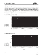
Discharge head h (m)
3
2
Flow-rate Q (m3/h)
.7
.8
.9
1
2
3
4
5
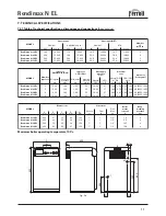
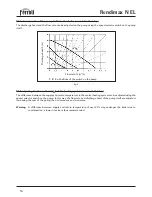
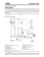
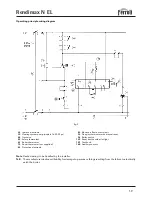
7.06 pressure drop as a function of heating system water fl ow-rate
7.07 Residual discharge head available to the heating system
(models 16-23-30 PV)
Note
The diagram in fig. 7 refers to the maximum heating pump discharge head/flow-rate with the speed selector
switch in position 3.
fig. 6
fig. 7
.03
.04
.05
.07 .08 .09 .1
.06
.3
.4
.5
.7 .8 .9 1
.6
.2
.2
.3
.4
.5
.6
.7
.8
.9
1
2
3
Pressure drop
∆
p (m)
Flow-rate Q (m3/h)


