background image

Pegasus F2 N T

3

1. Operating instructions............................................................................4

1.1 Introduction.............................................................................................................4
1.2 Control panel and main components .....................................................................4
1.3 Turning on and off...................................................................................................5
1.4 Adjustments ............................................................................................................7
1.5 Maintenance............................................................................................................8
1.6 Trouble ....................................................................................................................8

2. Installation ..............................................................................................9

2.1 General Instructions................................................................................................9
2.2 Place of installation .................................................................................................9
2.3 Plumbing connections.............................................................................................9
2.4 Gas connection .....................................................................................................10
2.5 Electrical Connections ..........................................................................................11
2.6 Connection to the fl ue ..........................................................................................12

3. Service and maintenance ......................................................................13

3.1 Adjustments ..........................................................................................................13
3.2 System start-up .....................................................................................................16
3.3 Maintenance..........................................................................................................17
3.4 Troubleshooting ................................................................................................... 21

4 Technical characteristics and data .........................................................23

4.1 Dimensions and connections ................................................................................23
4.2 General view and main components ....................................................................24
4.3 Technical data table ..............................................................................................25
4.4 Diagrams ...............................................................................................................26
4.5 Wiring diagrams....................................................................................................27


Summary of Contents for PEGASUS F2 N 2S

Page 1: ...cast iron gas boiler for central heating chaudi re gaz en fonte pour chauffage central INSTRUCTIONS FOR USE INSTALLATION AND MAINTENANCE INSTRUCTIONS D UTILISATION D INSTALLATION ET D ENTRETIEN cod 35...

Page 2: ...ted by the new owner and or installer Installation and maintenance must be carried out by professionally quali fied personnel according to current regulations and the manufacturer s instructions Incor...

Page 3: ...Place of installation 9 2 3 Plumbing connections 9 2 4 Gas connection 10 2 5 Electrical Connections 11 2 6 Connection to the flue 12 3 Service and maintenance 13 3 1 Adjustments 13 3 2 System start up...

Page 4: ...n elements whose particular shape guarantees high exchange efficiency under all operating conditions and an open flue main burner equipped with a pilot burner with piezoelectric ignition The boiler ou...

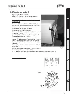
Page 5: ...pilot burner by repeatedly pressing the button of the piezoelectric igniter 8 fig 1 Once the pilot light is burning keep the gas valve knob pressed for approximately 15 to 20 seconds and then slowly r...

Page 6: ...s valve knob pressed for approximately 15 to 20 seconds and then slowly release it checking that the pilot light stays lit If it goes out wait for 30 seconds and repeat the ignition operation Power up...

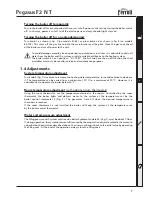
Page 7: ...ob 5 fig 1 clockwise to increase the heating water temperature turn anticlockwise to decrease it The temperature can be varied from a minimum of 30 C to a maximum of 90 C However it is advisable not t...

Page 8: ...h a soft damp cloth possibly soaked in soapy water Do not use any abrasive detergents and solvents 1 6 Anomalies Listed below are the anomalies that can be caused by simple user solvable problems Symb...

Page 9: ...ation must be free of dust flammable materials or objects or corrosive gases The room must be dry and not subject to freezing When positioning the boiler leave sufficient space around it for normal ma...

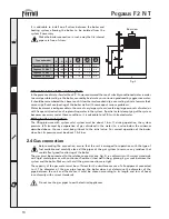
Page 10: ...water to a value below the minimum described above the user must bring it back to the initial value For correct operation of the boiler when hot its pressure must be about 1 5 2 bar 2 4 Gas connectio...

Page 11: ...ntroller see wiring diagrams in paragraph 4 5 In addition it is equipped with a three pole cable for connection to the electricity line The connections to the grid must be made with a permanent connec...

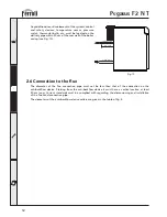
Page 12: ...andards must be complied with regarding the dimensioning and installation of the flues and connection pipe The diameters of the anti backflow device collars are given in the table of fig 5 Anyaddition...

Page 13: ...e to decrease it The pilot light adjustment is made without using instruments watching to see that the flame correctly envelops the thermocouple without burning too much gas To adjust this flame turn...

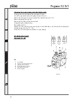
Page 14: ...urners from the manifold Change the main and pilot nozzles Reassemble carefully Perform the main nozzle gas pressure setting as described above and the pilot flame adjustment utilizing the gas valve f...

Page 15: ...rner gas pressure use the pressure point on the gas manifold pipe of the burner assembly see part 15 fig 19 HONEYWELL V4400C VALVE for mod 85 102 Key 1 Ignition button 2 Gas pressure adjustment screw...

Page 16: ...re no flammable liquids or materials in the immediate vicinity of the boiler Lighting the boiler Open the gas valve ahead of the boiler Vent the air from the pipe ahead of the gas valve Follow the use...

Page 17: ...ety thermostat with automatic reset This device prevents the water temperature in the system from exceeding boiling point The maximum intervention temperature is 110 C Automatic reset of the temperatu...

Page 18: ...3 Open the fume sampling point 4 Insert the probe 5 Adjust the boiler temperature to the maximum 6 Wait 10 15 minutes for the boiler to stabilize 7 Take the measurement Analyses made with an unstabil...

Page 19: ...tric igniter cable Unscrew the nut fixing the gas feed pipe ahead of the gas valve fig 14 On model 102 unscrew the 2 nuts Unscrew the two nuts attaching the combustion chamber door to the cast iron el...

Page 20: ...low device Remove the fume chamber closing plate and the associated insu lation Remove the burner unit see preceding paragraph Usingthebrushprovided cleanthefumeevacuationductsbetween the cast iron el...

Page 21: ...flame setting Check that the gas pressure is regular Pilot burner dirty Clean the pilot unit with compressed air Pilot light goes out Thermocouple defective Check or change the thermocouple Poor flame...

Page 22: ...r the heating system The control thermostat switches back on with too great a temperature difference Control thermostat broken Change the thermostat Thermostat bulb out of its sheath Check that the bu...

Page 23: ...ront view Side view Pegasus F2 N 51 T Pegasus F2 N 68 T Pegasus F2 N 85 T Pegasus F2 N 102 T 103 103 103 103 B 180 180 200 200 C 43 46 44 42 D 35 38 36 34 E Type and model 3 4 3 4 3 4 3 4 a3 Gas inlet...

Page 24: ...position 5 Boiler control thermostat 6 Piezoelectric igniter 7 Fume thermostat reset 8 Safety thermostat 9 Pressure temperature gauge 10 Arrangement for fitting a thermostatic controller 11 Automatic...

Page 25: ...0 mbar 13 3 Feed pressure G20 mbar 20 0 Delivery G25 nm3 h Main nozzles G25 mm 3 x 3 50 Pressure at burner G25 mbar Supply pressure G25 mbar 25 0 N elements 4 Delivery G31 kg h 4 34 Main nozzles G31 m...

Page 26: ...26 4 4 Diagrams Loss of head fig 20 1 2 3 4 5 6 7 8 9 10 0 1 0 2 0 3 0 4 0 5 0 6 0 7 0 8 0 9 1 2 Delivery m3 h Losses of head m column H 2 O Pegasus F2 N 51 T Pegasus F2 N 68 T Pegasus F2 N 85 T Pega...

Page 27: ...hermocouple 32 Circulator 44 Gas valve 49 Safety thermostat 63 Boiler control thermostat 72 Room thermostat not supplied 92 Fume thermostat with manual reset 98 Switch 159 Test button 160 Auxiliary co...

Page 28: ...taller Key 23 Thermocouple 32 Circulator 44 Gas valve 49 Safety thermostat 63 Boiler control thermostat 72 Room thermostat not supplied 92 Fume thermostat with manual reset 98 Switch 159 Test button 1...

Page 29: ...FERROLI S p A Via Ritonda 78 a 37047 San Bonifacio Verona ITALY www ferroli it...

Reviews: