Ferroli GFN K Instructions For Use, Installation & Maintenance Download Page 8

GFN K

36

GB

cod. 3540I190  -  10/2007  (Rev. 00)

2.3 Plumbing connections

The heating capacity of the unit must be previously established by calculating the building's heat requirement according
to current regulations. The system must be provided with all the components for correct and regular operation. It is ad-
visable to install on-off valves between the boiler and heating system allowing the boiler to be isolated from the system
if necessary.

B

The safety valve outlet must be connected to a funnel or collection pipe to prevent water spurting onto the floor
in case of overpressure in the heating circuit. Otherwise, if the drain valve is activated and floods the room,
the boiler manufacturer cannot be held liable.

Do not use the water system pipes to earth electrical appliances.

Before installation, carefully wash all the pipes of the system to remove residuals or impurities that could affect correct
operation of the unit.

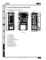
Carry out the relevant connections according to the diagram in cap. 4.1 "Dimensions and connections" and the symbols
given on the unit.

Characteristics of the water system

In the presence of water harder than 25° Fr (1°F = 10ppm CaCO3), use suitably treated water in order to avoid possible
scaling in the boiler. Treatment must not reduce the hardness to values below 15°F (Decree 236/88 for uses of water
intended for human consumption). Treatment of the water used is indispensable in case of very large systems or with
frequent introduction of replenishing water in the system.

Antifreeze system, antifreeze fluids, additives and inhibitors

If necessary, antifreeze fluids, additives and inhibitors can be used only if the manufacturer of these products guaran-
tees that they are suitable for this use and do not cause damage to the boiler exchanger or other components and/or
materials of the unit and system. Do not use antifreeze fluids, additives or inhibitors that are not specific for use in heat-
ing systems and not compatible with the boiler materials and system.

2.4 Conversion for use with an oil or pellet burner

An optional kit is available for use with an oil or pellet burner.

For installation, refer to the instructions contained in the kit.

2.5 Electrical connections

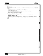
Accessing the electrical terminal block

To access the electrical terminal block 

1

fig. 3 lift the boiler cover.

fig. 3 - Accessing the terminal block

1

Summary of Contents for GFN K

Page 1: ...CTIONS FOR USE INSTALLATION AND MAINTENANCE INSTRUCTIONS D UTILISATION D INSTALLATION ET D ENTRETIEN UPUTE ZA UPORABU POSTAVLJANJE I ODR AVANJE INSTRUC IUNI DE UTILIZARE INSTALARE I NTRETINERE NAVODIL...

Page 2: ...instructions Incorrect installation or poor maintenance can cause damage or physical injury The manufacturer de clines any responsibility for damage caused by er rors in installation and use or by fai...

Page 3: ...of installation 35 2 3 Plumbing connections 36 2 4 Conversion for use with an oil or pellet burner 36 2 5 Electrical connections 36 2 6 Connection to the flue 37 3 Service and maintenance 38 3 1 Adjus...

Page 4: ...high heat efficiency performance and consider able energy saving The combustion chamber is specially designed to take large pieces of wood loading is by means of the large top door The combustion cham...

Page 5: ...auses a loss of efficiency Use wood logs dried outdoors and in the natural state stored for 2 years with max humidity of 20 Boiler lighting Open the bottom door and remove any ash present in the combu...

Page 6: ...nt knob to 60 C turning it to 80 C and adjusting the heating water temperature by means of the mixer valve would be optimum Load the combustion chamber with combustible material paper and wood and aft...

Page 7: ...s or materials corrosive gases volatile substances or dusts that can be sucked by the fan The room must be dry and not exposed to rain snow or frost A A space must be provided around the unit for remo...

Page 8: ...cs of the water system In the presence of water harder than 25 Fr 1 F 10ppm CaCO3 use suitably treated water in order to avoid possible scaling in the boiler Treatment must not reduce the hardness to...

Page 9: ...m opening of at least 3 mm interposing fuses of max 3A between the boiler and the line It is important to respect the polarities LINE brown wire NEUTRAL blue wire EARTH yellow green wire in making con...

Page 10: ...thing system Make sure there are no flammable liquids or materials in the immediate vicinity of the boiler Checks during operation Turn the unit on as described in sec 1 3 Check the seal of the water...

Page 11: ...ce the seal if necessary The control and safety devices must work properly The fume exhaust circuit must be perfectly efficient The fume ducts must be free of obstructions and leaks The water pressure...

Page 12: ...esium anode 130 Hot water tank circulating pump 178 Hot water tank thermometer bulb 180 Hot water tank 192 Recirculation 209 Hot water tank delivery 210 Hot water tank return 233 Hot water tank drain...

Page 13: ...filling cock 97 Magnesium anode 130 Hot water tank circulating pump 178 Hot water tank thermometer bulb 180 Hot water tank 192 Recirculation 209 Hot water tank delivery 210 Hot water tank return 233...

Page 14: ...bar 3 PMS Max heating temperature C 95 tmax Heating water content litres 28 Heating expansion tank capacity litres 10 Heating expansion tank prefilling pressure bar 1 Max working pressure in hot water...

Page 15: ...ied 72 Room thermostat not supplied 98 Switch 130 Hot water tank circulating pump 143 Hot water tank control thermostat 185 Summer Winter switch 239 Electrical heating element L N L N 72 32 130 L N 4...

Page 16: ...FERROLI S p A Via Ritonda 78 a 37047 San Bonifacio Verona ITALY www ferroli it...

Reviews: