


DOMINA N 80 DGT
41
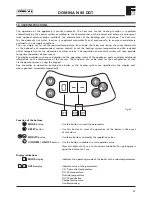
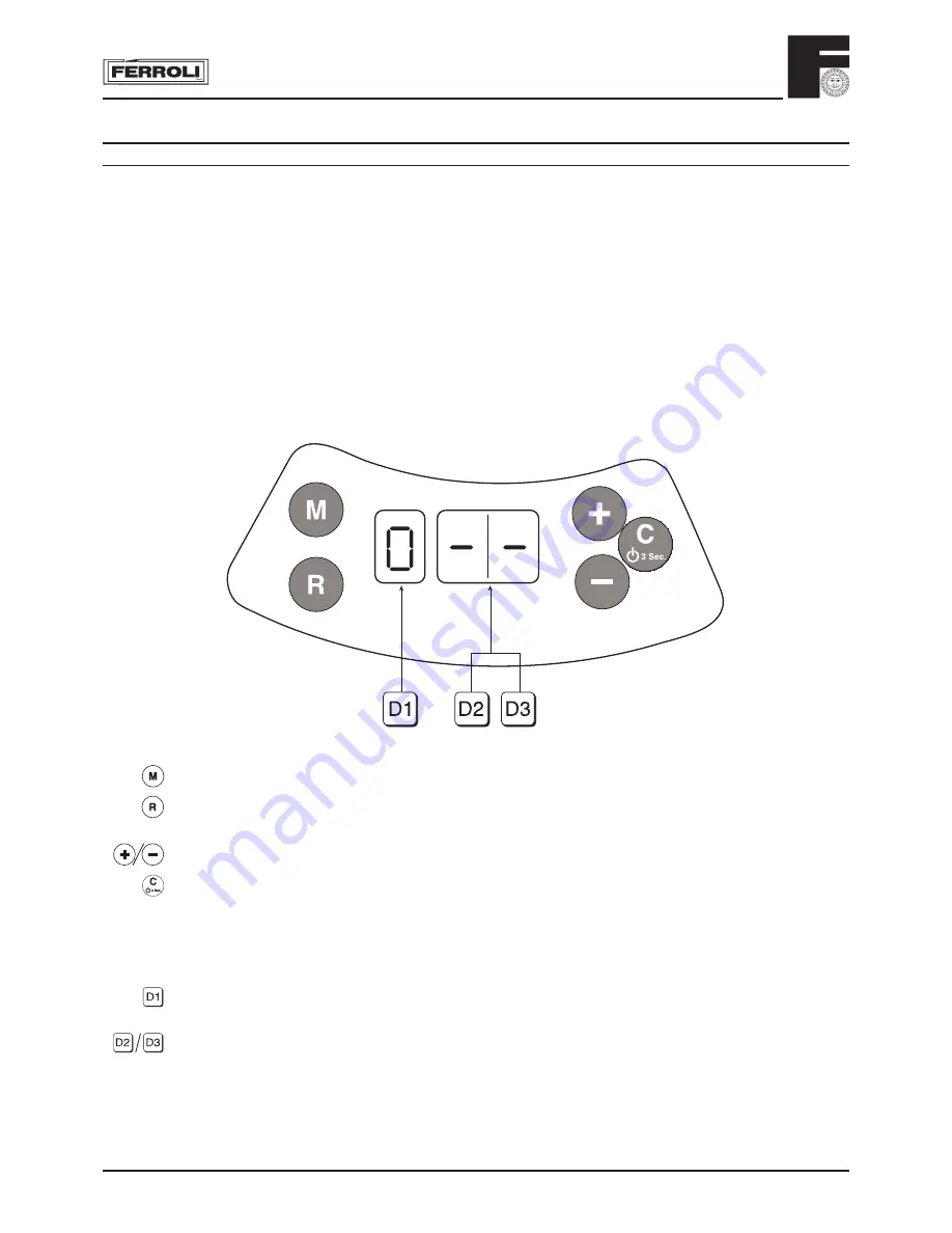
Fig. 45
10. USER INSTRUCTIONS
The operation of the appliance is mostly automatic. The heat rate for the heating function is regulated
automatically by the control system according to the characteristics of the internal and external environment
(with optional external probe installed), the characteristics of the building and its location. The heat rate
for the domestic hot water function is regulated automatically and continuously, to ensure rapid delivery
and comfort in all supply conditions.
The user simply has to set the required temperature from inside the living area (using the room thermostat
or the optional, yet recommended, remote control) or set the heating system temperature and the required
outlet temperature for the domestic hot water service. The regulation and control system will then provide
for optimal operation all year round.
The display provides continuous indication on the operating status of the appliance, and can display additional
information on the temperature of the sensors, the set-point, etc. or be used for the confi guration of such
via the operating menu, using the keypad.
Any anomalies in operation involving the boiler or the heating system are signalled on the display and,
where possible, corrected automatically.
MODE
button - Use this button to scroll the parameters.
RESET
button - Use this button to reset the operation of the boiler in the event
of shut-down.
MODIFY
button - Use these buttons to modify the regulation values.
CONFIRM / ON-OFF
button - Use this button to enable the set regulation value.
Press this button for 3 sec. to shut down the boiler. For igniting press
again the button for 3 sec.
MODE
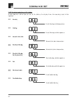
display - Indicates the operating mode of the boiler or the selected parameter.
DATA
display - Indicates value of the parameters:
C.H. fl ow outlet temperature
D.H.W. temperature
Outside temperature
D.H.W. production
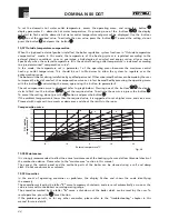
Compensation curve
Troubleshooting
Function of the buttons
Display indications
Summary of Contents for DOMINA N 80 DGT
Page 12: ...DOMINA N 80 DGT 12 3 01 Boiler Mounting Plate 149 178 131 Fig 13 ...
Page 46: ......
Page 47: ......


