Supplied By www.heating spares.co Tel. 0161 620 6677
23
DOMINA F 24 - 30 E
FERELLA F 24 - 30 MEL
MILOS AIR COMPACT E
Version - 09.2002
2.5 Fume circuit
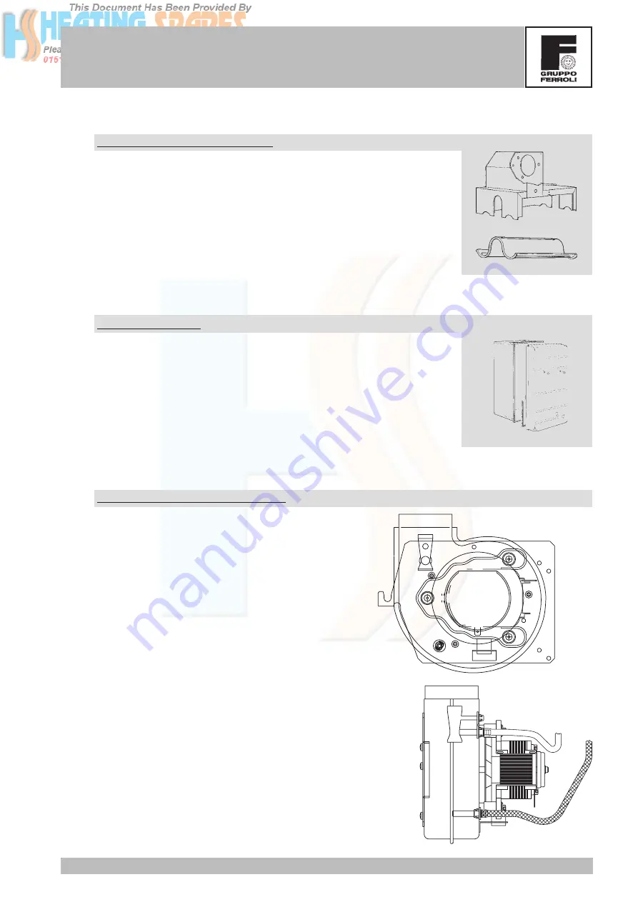
Fume deflector and manifold
All forced-flow boilers have a fume deflector above the exchanger whose
main task is to make the secondary air crossing the burners uniform, making
the flame homogeneous and stable. The fumes then reach a fume manifold
whose job is to make them move on to the fan.
Airtight chamber
Its task is to isolate the products of combustion from the area surrounding
the boiler. The airtight chamber contains all the components involved in the
fume routing. The wires and pipes coming out of its lower portion are
insulated with silicone seals, while its upper portion is fitted for hooking up
with the flues. The cover is sealed off with a porous plate and is fitted with
two plugs for using a probe to analyse the fumes and combustion air.
Fan and pressure switch points
Powered at 230V/50Hz by the card (X6 - 7/8), the fan has
the job of expelling the products of combustion from the
fume chamber. A plate is normally placed above the
exchanger to act as a deflector, make the incoming air
from the bottom of the burner uniform, make the flame
stable and obtain the required air/gas ratio. In order to
make sure the fan works properly, there are two pressure
points inside it. The first one detects a static pressure
signal that is positive, the second one detects a dynamic
pressure signal via an appropriate Venturi tube, which
is negative. With the difference in pressure detected by
the two test points it is possible to check whether the
fumes are adequately evacuated.


