


DOMIcondens F 24 D - F 28 D
32
EN
cod. 3541C751 - Rev. 00 - 10/2013
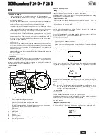
DHW temperature adjustment
Use the DHW buttons (details 1 and 2 - fig. 1) to adjust the temperature from a min. of
40°C to a max. of 50°C.
fig. 5
Room temperature adjustment (with optional room thermostat)
Using the room thermostat, set the temperature required in the rooms. If the room ther-
mostat is not installed, the boiler will keep the system at the set system delivery setpoint
temperature.
Room temperature adjustment (with optional remote timer control)
Using the remote timer control, set the required temperature in the rooms. The boiler will
adjust the system water according to the required room temperature. For operation with
remote timer control, please refer to the relevant instruction manual.
ECO/COMFORT selection
The unit has a function that ensures a high domestic hot water delivery speed and max-
imum comfort for the user. When the device is activated (COMFORT mode), the water
contained in the boiler is kept hot, thereby ensuring immediate availability of hot water
on opening the tap, without waiting times.
The user can deactivate the device (ECO mode) by pressing the
eco/comfort
button
(detail 7 - fig. 1). In ECO mode the display activates the ECO symbol (detail 12 - fig. 1).
To activate the COMFORT mode, press the
eco/comfort
button (detail 7 - fig. 1) again.
Sliding Temperature
When the optional external probe is installed, the boiler adjustment system works with
"Sliding Temperature”. In this mode, the temperature of the heating system is controlled
according to the outside weather conditions, to ensure high comfort and energy saving
throughout the year. In particular, the system delivery temperature is decreased as the
outside temperature increases, according to a specific "compensation curve”.
With Sliding Temperature adjustment, the temperature set with the heating buttons (de-
tail 3 - fig. 1) becomes the maximum system delivery temperature. It is advisable to set
a maximum value to allow system adjustment throughout its useful operating range.
The boiler must be adjusted at the time of installation by qualified personnel. Possible
adjustments can in any case be made by the user to improve comfort.
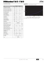
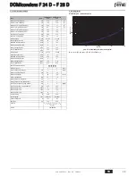
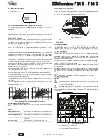
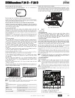
Compensation curve and curve offset
Press the
reset
button (detail 6 - fig. 1) for 5 seconds to access the "Sliding temperature"
menu; the display shows "CU" flashing.
Use the DHW buttons (detail 1 - fig. 1) to adjust the curve from 1 to 10 according to the
characteristic. By setting the curve to 0, sliding temperature adjustment is disabled.
Press the heating buttons (detail 3 - fig. 1) to access parallel curve offset; the display
shows "OF" flashing. Use the DHW buttons (detail 1 - fig. 1) to adjust the parallel curve
offset according to the characteristic (fig. 6).
Press the
reset
button (detail 6 - fig. 1) again for 5 seconds to exit the "Sliding Temper-
ature" menu.
If the room temperature is lower than the required value, it is advisable to set a higher
order curve and vice versa. Proceed by increasing or decreasing in steps of one and
check the result in the room.
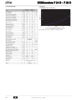
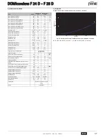
fig. 6 - Example of compensation parallel curve offset
Adjustments from Remote Timer Control
A
If the Remote Timer Control (optional) is connected to the boiler, the above ad-
justments are managed according to that given in table 1.
Table. 1
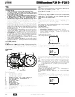
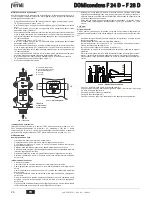
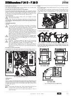
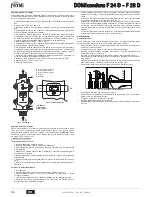
System water pressure adjustment
The filling pressure with system cold, read on the boiler water gauge (detail 2 - fig. 7),
must be approx. 1.0 bar. If the system pressure falls to values below minimum, the boiler
stops and fault
F37
is displayed. Bring it to the initial value using the filling cock detail 1
fig. 7. At the end of the operation always close the filling cock.
fig. 7 - Filling cock
A
Open
B
Closed
3. INSTALLATION
3.1 General Instructions
BOILER INSTALLATION MUST ONLY BE PERFORMED BY QUALIFIED PERSON-
NEL, IN ACCORDANCE WITH ALL THE INSTRUCTIONS GIVEN IN THIS TECHNICAL
MANUAL, THE PROVISIONS OF CURRENT LAW, THE PRESCRIPTIONS OF NA-
TIONAL AND LOCAL STANDARDS AND THE RULES OF PROPER WORKMANSHIP.
3.2 Place of installation
The combustion circuit is sealed with respect to the place of installation, therefore the
unit can be installed in any room. However, the place of installation must be sufficiently
ventilated to prevent the creation of dangerous conditions in case of even small gas
leaks. This safety standard is required by EEC Directive no. 2009/142 for all gas units,
including those with sealed chamber.
The unit is suitable for operation in a partially protected place in compliance with EN 297
pr A6, for temperatures to -5°C. It is advisable to install the boiler under the slope of a
roof, inside a balcony or in a sheltered recess.
Therefore the place of installation must be free of dust, flammable materials or objects
or corrosive gases.
The boiler is arranged for wall mounting and comes standard with a hooking bracket. Fix
the bracket to the wall according to the measurements given in the cover drawing and
hook the boiler on it. Wall fixing must ensure stable and effective support for the gener-
ator.
A
If the unit is enclosed in a cabinet or mounted alongside, a space must be pro-
vided for removing the casing and for normal maintenance operations
3.3 Plumbing connections
Important
B
The safety valve outlet must be connected to a funnel or collection pipe to pre-
vent water spurting onto the floor in case of overpressure in the heating circuit.
Otherwise, if the discharge valve cuts in and floods the room, the boiler manu-
facturer cannot be held liable.
B
Before making the connection, check that the unit is arranged for operation with
the type of fuel available and carefully clean all the system pipes.
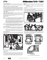
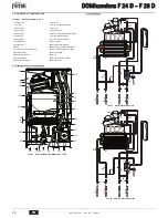
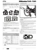
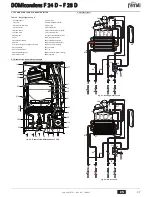
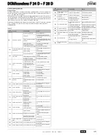
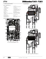
Carry out the relevant connections according to the diagram in fig. 8and the symbols giv-
en on the unit.
fig. 8 - Plumbing connections
1 =
System delivery -
2 =
DHW outlet
3 =
Gas inlet -
4 =
Cold water inlet
5 =
System return -
6 =
Safety valve drain
Heating temperature setting
Adjustment can be made from the Remote Timer Control menu and the
boiler control panel.
Hot water temperature adjustment
Adjustment can be made from the Remote Timer Control menu and the
boiler control panel.
Summer/Winter Switchover
Summer mode has priority over a possible Remote Timer Control heat-
ing demand.
Eco/Comfort selection
Adjustment can only be made from the boiler control panel.
I I I I
II
II
I
20
30
40
50
60
70
80
90
85
20
30
40
50
60
70
80
90
85
1
2
3
4
5
6
8
9
10
7
1
2
3
4
5
6
8
9
10
7
OFFSET = 20
OFFSET = 40
A
B
2
1
36 60 60
89
95
60
159
206
4
1
3
6
5
2


