background image

ATLAS ECO 30 SI UNIT

41

FR

cod. 3541Q551  -  Rev. 00  -  09/2019

Allumage de la chaudière

Ouvrir les vannes d'arrêt du combustible

Mettre l'appareil sous tension

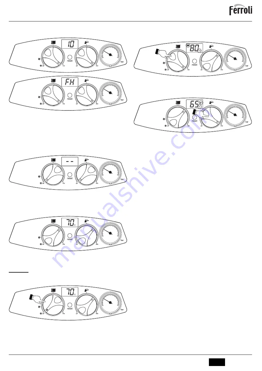
fig. 6 - Allumage de la chaudière

Pendant les 120 secondes qui suivent, l'afficheur visualise FH (cycle de purge de
l'air du circuit de chauffage).

Pendant les 5 premières secondes, l'afficheur visualise également la version du lo-
giciel de la carte

Dès que l'indication FH disparaît, la chaudière est prête à fonctionner automatique-
ment chaque fois que l'on prélève de l'eau chaude sanitaire ou en présence d'une
demande de la part du thermostat d'ambiance.

Extinction de la chaudière

Tourner les deux manettes en les positionnant sur le minimum (rep. 1 et 2 - fig. 1).

fig. 7 - Extinction de la chaudière

Au moment où l'on éteint la chaudière, la carte électronique reste encore sous tension.
Le fonctionnement eau sanitaire et chauffage est désactivé. Le système antigel reste actif.
Pour rallumer la chaudière, mettre les deux manettes (rep. 1 et 2 - fig. 1) sur les tempéra-
tures choisies.

fig. 8

La chaudière est prête à fonctionner immédiatement chaque fois que l'on prélève de
l'eau chaude sanitaire (puisage) ou en présence d'une signalisation de besoin par le
thermostat d'ambiance.

2.4 Réglages
Commutation Été/Hiver

Tourner uniquement la manette du chauffage sur le minimum (Été) (rep. 1 - fig. 1).

fig. 9

La chaudière ne fournira que de l'eau chaude sanitaire. Le système antigel reste actif.
Pour désactiver le mode Été (Hiver), tourner la manette du chauffage (rep. 1 - fig. 1) sur
la température choisie.

Réglage de la température de chauffage

Agir sur la manette du chauffage (rep. 1 - fig. 1) pour régler la température entre 30 °C
(minimum) et 80 °C (maximum).

Toutefois, il est conseillé de ne pas faire fonctionner la chaudière en dessous de 45 °C

.

fig. 10

Réglage de la température d'eau chaude sanitaire

Agir sur la manette ECS (rep. 2 - fig. 1) pour régler la température entre 50 °C (minimum)
et 75 °C (maximum).

fig. 11

Régulation de la température ambiante (par thermostat d'ambiance en option)

Programmer à l'aide du thermostat d'ambiance la température souhaitée à l'intérieur des
pièces. Si le thermostat d'ambiance n'est pas monté, la chaudière maintiendra la tem-
pérature dans l'installation à la consigne départ.

Régulation de la température ambiante (par chronocommande à distance en option)

Programmer à l'aide de la chronocommande à distance la température souhaitée à l'in-
térieur des pièces. La chaudière réglera la température dans le circuit d'eau de l'instal-
lation en fonction de la température ambiante demandée. Pour le fonctionnement par
chronocommande à distance, se reporter au manuel d'utilisation spécifique.

Sélection ECO/CONFORT

L’appareil est doté d'une fonction qui garantit une vitesse élevée de débit d'ECS et un
confort optimal pour l'utilisateur Lorsque le dispositif est en fonction (mode CONFORT),
l’eau contenue dans la chaudière est maintenue en température, ce qui permet d'obtenir
immédiatement l'eau chaude à la sortie de la chaudière, dès l'ouverture du robinet, évi-
tant ainsi un temps d'attente.
Le dispositif peut être désactivé par l'utilisateur (mode ECO) en appuyant sur la touche

reset

 (rep. 3 - fig. 1). Le symbole Confort (rep. 8 - fig. 1) sera désactivé et l'afficheur vi-

sualisera 3 secondes 

« EC »

 (ECO).

Pour activer le mode CONFORT, réappuyer sur la touche 

reset

 (rep. 3 - fig. 1). Le sym-

bole Confort (rep. 8 - fig. 1) sera activé et l'afficheur visualisera 3 secondes 

« CO »

(CONFORT).

Température évolutive

Si la sonde extérieure (option) est montée, le système de réglage de la chaudière tra-
vaillera en « Température évolutive ». Dans ce mode, la température de l'installation
chauffage est régulée en fonction des conditions climatiques extérieures de manière à
garantir un confort élevé et une économie d'énergie pendant toute l'année En particulier,
lorsque la température extérieure augmente la température de départ installation dimi-
nue selon une "courbe de compensation" donnée.
Avec le réglage évolutif, la température sélectionnée par la touche chauffage (rep. 3 -
fig. 1) devient la température maximum de refoulement de l'installation. Il est conseillé
de régler la valeur maximale pour permettre au système de réguler la température sur
toute la plage utile de fonctionnement
La chaudière doit être réglée au cours de l'installation par un professionnel qualifié Noter
que l'utilisateur pourra faire des adaptations ou ajustements éventuels pour améliorer le
confort

0

120

60

80

100

40

20

0

120

60

80

100

40

20

0

120

60

80

100

40

20

0

120

60

80

100

40

20

0

120

60

80

100

40

20

0

120

60

80

100

40

20

0

120

60

80

100

40

20

Summary of Contents for ATLAS ECO 30 SI UNIT

Page 1: ...TRUCCIONES DE USO INSTALACIÓN Y MANTENIMIENTO EN INSTRUCTIONS FOR USE INSTALLATION AND MAINTENANCE FR INSTRUCTIONS D UTILISATION D INSTALLATION ET D ENTRETIEN NL AANWIJZINGEN VOOR GEBRUIK INSTALLATIE EN ONDERHOUD PL INSTRUKCJA OBSłUGI INSTALACJI I KONSERWACJI EL Ο ΗΓΊΕΣ ΧΡΉΣΗΣ ΕΓΚΑΤΆΣΤΑΣΗΣ ΚΑΙ ΣΥΝΤΉΡΗΣΗΣ 3541Q551 ...

Page 2: ...olo se sottoposti a sorveglianza In caso di dubbio non utilizzare l apparecchio e rivolgersi al fornitore Lo smaltimento dell apparecchio e dei suoi accessori deve essere effettuato in modo adeguato in conformità alle norme vigenti Le immagini riportate nel presente manuale sono una rappresentazione semplificata del prodotto In questa rappresentazione possono esserci lievi e non significative diff...

Page 3: ...ata impianto impostata Regolazione della temperatura ambiente con cronocomando remoto opzionale Impostare tramite il cronocomando remoto la temperatura ambiente desiderata all inter no dei locali La caldaia regolerà l acqua impianto in funzione della temperatura ambien te richiesta Per quanto riguarda il funzionamento con cronocomando remoto fare riferimento al relativo manuale d uso Selezione ECO...

Page 4: ...ere il tasto reset part 3 fig 1 fig 13 Spostamento parallelo delle curve Ruotando nuovamente la manopola riscaldamento part 1 fig 1 e successivamente premendo il tasto Reset part 3 fig 1 per 5 secondi si esce dalla modalità regolazione delle curve parallele Se la temperatura ambiente risulta inferiore al valore desiderato si consiglia di impostare una curva di ordine superiore e viceversa Proceder...

Page 5: ...icienza Per un corretto funzionamento della caldaia ATLAS ECO 30 SI UNIT il selettore di ve locità vedi fig 16 deve essere posizionato sulla posizione III fig 16 Caratteristiche dell acqua impianto In presenza di acqua con durezza superiore ai 25 Fr 1 F 10ppm CaCO3 si prescrive l uso di acqua opportunamente trattata al fine di evitare possibili incrostazioni in caldaia Il trattamento non deve ridu...

Page 6: ...o scopo resistente cioè alla temperatura ed alla corrosione Nei punti di giunzione si raccomanda di curare la tenuta e di isolare termicamente tutto il condotto tra caldaia e camino per evitare la formazione di condensa 4 SERVIZIO E MANUTENZIONE Tutte le operazioni di regolazione trasformazione messa in servizio manutenzione de scritte di seguito devono essere effettuate solo da Personale Qualific...

Page 7: ...sa in servizio B Verifiche da eseguire alla prima accensione e dopo tutte le operazioni di ma nutenzione che abbiano comportato la disconnessione dagli impianti o un inter vento su organi di sicurezza o parti della caldaia Prima di accendere la caldaia Aprire le eventuali valvole di intercettazione tra caldaia ed impianti Verificare la tenuta dell impianto combustibile Verificare la corretta preca...

Page 8: ...positivi di comando e di sicurezza devono funzionare correttamente Il circuito di evacuazione fumi deve essere in perfetta efficienza Controllare che non ci siano eventuali occlusioni o ammaccature nei tubi di alimen tazione e ritorno del combustibile Effettuare la pulizia del filtro di linea di aspirazione del combustibile Rilevare il corretto consumo di combustibile Effettuare la pulizia della t...

Page 9: ...nell impianto Verificare il circolatore Vedi tabella 4 Presenza aria nell impianto Sfiatare l impianto A04 Anomalia parametri scheda Errata impostazione parametro scheda Verificare ed eventualmente modifi care il parametro scheda F07 Anomalia preriscalda tore non chiude il con tatto in 120 secondi Cablaggio interrotto Verificare il cablaggio F09 Anomalia parametri scheda Errata impostazione parame...

Page 10: ...olatore riscaldamento 36 sfiato aria automatico 38 Flussostato 56 Vaso di espansione 74 Rubinetto di riempimento impianto 95 Valvola deviatrice 114 Pressostato acqua 194 Scambiatore sanitario 209 Uscita acqua calda sanitaria 210 Entrata acqua fredda sanitaria 255 Scarico acqua impianto 278 Sensore doppio Sicurezza riscaldamento 295 Bruciatore 295 278 500 36 194 38 74 32 95 114 210 290 145 50 850 7...

Page 11: ...max esercizio riscaldamento bar 3 PMS Pressione min esercizio riscaldamento bar 0 8 Temperatura max riscaldamento C 100 tmax Contenuto acqua riscaldamento litri 20 Capacità vaso di espansione riscaldamento litri 10 Pressione precarica vaso di espansione riscaldamento bar 1 Pressione max di esercizio sanitario bar 9 PMW Pressione min di esercizio sanitario bar 0 3 Portata sanitaria t 25 C l min 14 ...

Page 12: ...Ğů ďƌƵĐŝĂƚŽƌĞ Ěŝ ĂĐĐĞŶƐŝŽŶĞ ŽŶƐƵŵŽ ĞŶĞƌŐĞƚŝĐŽ ĂŶŶƵŽ ŝǀĞůůŽ ĚĞůůĂ ƉŽƚĞŶnjĂ ƐŽŶŽƌĂ Ăůů ŝŶƚĞƌŶŽ ŵŝƐƐŝŽŶŝ Ěŝ ŽƐƐŝĚŝ Ěŝ ĂnjŽƚŽ WƌŽĨŝůŽ Ěŝ ĐĂƌŝĐŽ ĚŝĐŚŝĂƌĂƚŽ ůĂƐƐĞ Ěŝ ĞĨĨŝĐŝĞŶnjĂ ĞŶĞƌŐĞƚŝĐĂ Ěŝ ƌŝƐĐĂůĚĂŵĞŶƚŽ ĚĞůů ĂĐƋƵĂ ĚĂ н Ă Ϳ ŽŶƐƵŵŽ ŐŝŽƌŶĂůŝĞƌŽ Ěŝ ĞŶĞƌŐŝĂ ĞůĞƚƚƌŝĐĂ ŽŶƐƵŵŽ ĂŶŶƵŽ Ěŝ ĞŶĞƌŐŝĂ ĞůĞƚƚƌŝĐĂ ĨĨŝĐŝĞŶnjĂ ĞŶĞƌŐĞƚŝĐĂ Ěŝ ƌŝƐĐĂůĚĂŵĞŶƚŽ ĚĞůů ĂĐƋƵĂ ŽŶƐƵŵŽ ŐŝŽƌŶĂůŝĞƌŽ Ěŝ ĐŽŵďƵƐƚŝďŝůĞ ŽŶƐƵŵŽ ĂŶŶƵŽ Ěŝ ĐŽŵďƵƐƚŝď...

Page 13: ...e 95 Valvola deviatrice 114 Pressostato acqua 138 Sonda esterna opzionale 139 Cronocomando Remoto opzionale 278 Sensore doppio Sicurezza riscaldamento TR Trasformatore d accensione FR Fotoresistenza MB Motore bruciatore VE Valvola elettromagnetica DBM06F T T 278 L N 4 5 6 7 8 9 10 11 12 13 14 15 16 17 18 L N 230V 50Hz 38 32 138 139 72 TR MB 1 M VE FR 1 2 95 CPD06 114 1 4 1 4 ...

Page 14: ...ƐƐĂ ƐĐůƵƐŝŽŶŝ ŽŶŽ ĞƐĐůƵƐŝ ĚĂůůĂ ƉƌĞƐĞŶƚĞ ŐĂƌĂŶnjŝĂ ŝ ĚŝĨĞƫ Ěŝ ĐŽŶĨŽƌŵŝƚă ĐĂƵƐĂƟ ĚĂ ͻ ƚƌĂƐƉŽƌƚŽ ŶŽŶ ĞīĞƩƵĂƚŽ Ă ĐƵƌĂ ĚĞůů ĂnjŝĞŶĚĂ ƉƌŽĚƵƩƌŝĐĞ ͻ ĂŶŽƌŵĂůŝƚă Ž ĂŶŽŵĂůŝĞ Ěŝ ƋƵĂůƐŝĂƐŝ ŐĞŶĞƌĞ ŶĞůů ĂůŝŵĞŶƚĂnjŝŽŶĞ ĚĞŐůŝ ŝŵƉŝĂŶƟ ŝĚƌĂƵůŝĐŝ ĞůĞƩƌŝĐŝ Ěŝ ĞƌŽŐĂnjŝŽŶĞ ĚĞů ĐŽŵďƵƐƟďŝůĞ Ěŝ ĐĂŵŝŶŝ Ğ Ž ƐĐĂƌŝĐŚŝ ͻ ĐĂůĐĂƌĞ ŝŶĂĚĞŐƵĂƟ ƚƌĂƩĂŵĞŶƟ ĚĞůů ĂĐƋƵĂ Ğ Ž ƚƌĂƩĂŵĞŶƟ ĚŝƐŝŶĐƌŽƐƚĂŶƟ ĞƌƌŽŶĞĂŵĞŶƚĞ ĞīĞƩƵĂƟ ͻ ĐŽƌƌŽƐŝŽŶŝ ĐĂƵƐĂƚĞ ĚĂ...

Page 15: ...orios de acuerdo con las normas vigentes Las imágenes contenidas en este manual son una representación simplificada del producto Dicha representación puede tener diferencias ligeras y no significativas con respecto al producto suministrado 2 INSTRUCCIONES DE USO 2 1 Presentación Estimado cliente Nos complace que haya adquirido FERROLI una caldera de diseño avanzado tecnolo gía de vanguardia elevad...

Page 16: ...temperatura de ida prefijada Regulación de la temperatura ambiente con el reloj programador a distancia opcional Mediante el reloj programador a distancia establecer la temperatura ambiente deseada en el interior de la vivienda La caldera regula el agua de la calefacción en función de la temperatura ambiente requerida Por lo que se refiere al funcionamiento con el reloj pro gramador a distancia co...

Page 17: ...13 que se puede modificar con el mando del agua sanitaria 2 fig 1 pulsando después la tecla reset 3 fig 1 fig 13 Desplazamiento paralelo de las curvas Si se gira otra vez el mando de la calefacción 1 fig 1 y después se pulsa la tecla Reset 3 fig 1 durante 5 segundos se sale de la modalidad de regulación de las curvas pa ralelas Si la temperatura ambiente es inferior al valor deseado se aconseja se...

Page 18: ... en el aparato Circulador de alta eficiencia Para que la caldera ATLAS ECO 30 SI UNIT funcione correctamente el selector de ve locidad fig 16 debe situarse en la posición III fig 16 Características del agua de la instalación En presencia de agua de dureza superior a 25 Fr 1 F 10 ppm CaCO3 es necesario usar agua adecuadamente tratada a fin de evitar posibles incrustaciones en la caldera El tratamie...

Page 19: ...peratura y a la corrosión En los puntos de unión se recomienda controlar la hermeticidad y aislar tér micamente todo el conducto entre caldera y chimenea a fin de evitar la formación de condensación 4 SERVICIO Y MANTENIMIENTO Todas las operaciones de regulación transformación puesta en servicio y manteni miento que se describen a continuación deben ser efectuadas exclusivamente por un técnico auto...

Page 20: ...rvicio B Controles que se han de efectuar durante el primer encendido tras las opera ciones de mantenimiento que exijan desconectar la caldera y después de cual quier intervención en los dispositivos de seguridad o componentes de la caldera Antes de encender la caldera Abrir las válvulas de corte si las hay entre la caldera y las instalaciones Verificar la estanqueidad del sistema del combustible ...

Page 21: ...iento correcto de los dispositivos de mando y seguridad Comprobar la eficacia de la tubería de salida de humos Controlar que no haya obstrucciones o abolladuras en los tubos de entrada y retor no del combustible Limpiar el filtro de la tubería de entrada de combustible Comprobar que el consumo de combustible sea correcto Limpiar el cabezal de combustión en la zona de salida del combustible en el d...

Page 22: ...ire la instalación A04 Anomalía de los pará metros de la tarjeta Parámetro de la tarjeta mal configurado Controlar el parámetro de la tarjeta y modificarlo si es necesario F07 Anomalía del preca lentador no cierra el contacto en 120 s Cableado interrumpido Controlar el cableado F09 Anomalía de los pará metros de la tarjeta Parámetro de la tarjeta mal configurado Controlar el parámetro de la tarjet...

Page 23: ... de seguridad 32 Circulador de calefacción 36 Purgador de aire automático 38 Flujostato 56 Vaso de expansión 74 Llave de llenado de la instalación 95 Válvula desviadora 114 Presostato del agua 194 Intercambiador AS 209 Salida de ACS 210 Entrada de AFS 255 Descarga de agua de la instalación 278 Sensor doble seguridad calefacción 295 Quemador 295 278 500 36 194 38 74 32 95 114 210 290 145 50 850 78 ...

Page 24: ...máx 80 60 C 93 7 Rendimiento 30 98 2 Presión máxima en calefacción bar 3 PMS Presión mínima en calefacción bar 0 8 Temperatura máxima agua calefacción C 100 tmáx Contenido agua de calefacción litros 20 Capacidad vaso expansión calefacción litros 10 Presión de precarga vaso expansión calefacción bar 1 Presión máxima en ACS bar 9 PMW Presión mínima en ACS bar 0 3 Caudal de AS t 25 C l min 14 3 Cauda...

Page 25: ...Ě ĚĞů ƋƵĞŵĂĚŽƌ ĚĞ ĞŶĐĞŶĚŝĚŽ ŽŶƐƵŵŽ ĂŶƵĂů ĚĞ ĞŶĞƌպà EŝǀĞů ĚĞ ƉŽƚĞŶĐŝĂ ĂĐƷƐƚŝĐĂ ŵŝƐŝŽŶĞƐ ĚĞ ſdžŝĚŽƐ ĚĞ ŶŝƚƌſŐĞŶŽ WĞƌĨŝů ĚĞ ĐĂƌŐĂ ĚĞĐůĂƌĂĚŽ ůĂƐĞ ĞĨŝĐŝĞŶĐŝĂ ĞŶĞƌŐĠƚŝĐĂ ĚĞů ĐĂůĚĞŽ ĚĞ ĂŐƵĂ ĚĞ н Ă Ϳ ŽŶƐƵŵŽ ĚŝĂƌŝŽ ĚĞ ĞůĞĐƚƌŝĐŝĚĂĚ ŽŶƐƵŵŽ ĂŶƵĂů ĚĞ ĞůĞĐƚƌŝĐŝĚĂĚ ĨŝĐŝĞŶĐŝĂ ĞŶĞƌŐĠƚŝĐĂ ĚĞů ĐĂůĚĞŽ ĚĞ ĂŐƵĂ ŽŶƐƵŵŽ ĚŝĂƌŝŽ ĚĞ ĐŽŵďƵƐƚŝďůĞ ŽŶƐƵŵŽ ĂŶƵĂů ĚĞ ĐŽŵďƵƐƚŝďůĞ DĂƌĐĂ ĐŽŵĞƌĐŝĂů ZZK ĂůĚĞƌĂ ĚĞ ĐŽŶĚĞŶƐĂĐŝſŶ EK ĂůĚĞƌĂ...

Page 26: ...ional 95 Válvula desviadora 114 Presostato del agua 138 Sonda exterior opcional 139 Cronomando remoto opcional 278 Sensor doble seguridad calefacción TR Transformador de encendido FR Fotorresistencia MB Motor quemador VE Válvula electromagnética DBM06F T T 278 L N 4 5 6 7 8 9 10 11 12 13 14 15 16 17 18 L N 230V 50Hz 38 32 138 139 72 TR MB 1 M VE FR 1 2 95 CPD06 114 1 4 1 4 ...

Page 27: ...S L U FÉRROLI ESPAÑA S L U durante el período de garantía durante el período de garantía Si el montaje no respeta las instrucciones que se suministran en la máquina Si el montaje no respeta las instrucciones que se suministran en la máquina La instalación de la máquina no respeta las Leyes y Reglamentaciones en vigor electricidad hidráulicas combustibles La instalación de la máquina no respeta las...

Page 28: ... appropriately disposed of in compliance with current regulations The images given in this manual are a simplified representation of the product In this repre sentation there may be slight and insignificant differences with respect to the product sup plied 2 OPERATING INSTRUCTIONS 2 1 Introduction Dear Customer Thank you for choosing a FERROLI boiler featuring advanced design cutting edge tech nol...

Page 29: ...t temperature Room temperature adjustment with optional remote timer control Using the remote timer control set the temperature desired in the rooms The boiler unit will set the system water according to the required room temperature For information on the remote timer control please refer to its user s manual ECO COMFORT selection The unit has a function that ensures a high domestic hot water del...

Page 30: ...rve offset fig 13 which can be modified with the DHW knob detail 2 fig 1 then press the reset button detail 3 fig 1 fig 13 Parallel curve offset Turn the heating knob detail 1 fig 1 and then press the Reset button detail 3 fig 1 for 5 seconds to exit the parallel curve adjustment mode If the room temperature is lower than the desired value it is advisable to set a higher or der curve and vice vers...

Page 31: ... the diagram in cap 5 and the symbols given on the unit High efficiency circulating pump For proper operation of the boiler ATLAS ECO 30 SI UNIT the speed selector see fig 16 must be set to position III fig 16 Characteristics of the water system In the presence of water harder than 25 Fr 1 F 10ppm CaCO3 use suitably treated water in order to avoid possible scaling in the boiler Treatment must not ...

Page 32: ... be made from material suitable for the purpose i e heat and corrosion resistant Ensure the seal at the joints and insulate the entire pipe between boiler and flue to prevent the formation of condensate 4 SERVICE AND MAINTENANCE All adjustment conversion commissioning and maintenance operations described be low must only be carried out by Qualified Personnel meeting the professional technical requ...

Page 33: ...fig 28 Position of electrodes baffle 4 2 Commissioning B Checks to be done at first lighting and after all maintenance operations that in volved disconnection from the systems or work on safety devices or parts of the boiler Before lighting the boiler Open any on off valves between the boiler and the systems Check the tightness of the fuel system Check the pre filling of the expansion tank Fill th...

Page 34: ...he following The control and safety devices must function correctly The fume exhaust circuit must be perfectly efficient Check there are no obstructions or dents in the fuel supply and return pipes Clean the filter of the fuel suction line Measure the correct fuel consumption Clean the combustion head in the fuel outlet zone on the swirl disc Leave the burner running at full rate for approximately...

Page 35: ...eration of the heating sensor No water circulation in the system Check the circulating pump See table 4 Air in the system Vent the system A04 Card parameter fault Wrong card parameter setting Check the card parameter and modify it if necessary F07 Preheater fault the contact does not close in 120 seconds Wiring disconnected Check the wiring F09 Card parameter fault Wrong card parameter setting Che...

Page 36: ...turn 14 Safety valve 32 Heating circulating pump 36 automatic air vent 38 Flow switch 56 Expansion tank 74 System filling cock 95 Diverter valve 114 Water pressure switch 194 DHW exchanger 209 DHW outlet 210 Cold water inlet 255 System water drain 278 Double sensor Safety heating 295 Burner 295 278 500 36 194 38 74 32 95 114 210 290 145 50 850 78 639 210 63 309 63 98 65 14 10 8 11 9 Ø120 130 630 9...

Page 37: ...98 2 Max working pressure in heating bar 3 PMS Min working pressure in heating bar 0 8 Max heating temperature C 100 tmax Heating water content litres 20 Heating expansion tank capacity litres 10 Heating expansion tank prefilling pressure bar 1 Max working pressure in hot water production bar 9 PMW Min working pressure in hot water production bar 0 3 DHW flow rate t 25 C l min 14 3 DHW flow rate t...

Page 38: ...ƵƌĞ ƌĞŐŝŵĞ ΎΎͿ ƚ ĨƵůů ůŽĂĚ ƚ ƉĂƌƚ ůŽĂĚ Ŷ ƐƚĂŶĚďLJ ŵŽĚĞ ƚĂŶĚďLJ ŚĞĂƚ ůŽƐƐ ŐŶŝƚŝŽŶ ďƵƌŶĞƌ ƉŽǁĞƌ ĐŽŶƐƵŵƉƚŝŽŶ ŶŶƵĂů ĞŶĞƌŐLJ ĐŽŶƐƵŵƉƚŝŽŶ ŽƵŶĚ ƉŽǁĞƌ ůĞǀĞů ŵŝƐƐŝŽŶƐ ŽĨ ŶŝƚƌŽŐĞŶ ŽdžŝĚĞƐ ĞĐůĂƌĞĚ ůŽĂĚ ƉƌŽĨŝůĞ tĂƚĞƌ ŚĞĂƚŝŶŐ ĞŶĞƌŐLJ ĞĨĨŝĐŝĞŶĐLJ ĐůĂƐƐ ĨƌŽŵ н ƚŽ Ϳ ĂŝůLJ ĞůĞĐƚƌŝĐŝƚLJ ĐŽŶƐƵŵƉƚŝŽŶ ŶŶƵĂů ĞůĞĐƚƌŝĐŝƚLJ ĐŽŶƐƵŵƉƚŝŽŶ tĂƚĞƌ ŚĞĂƚŝŶŐ ĞŶĞƌŐLJ ĞĨĨŝĐŝĞŶĐLJ ĂŝůLJ ĨƵĞů ĐŽŶƐƵŵƉƚŝŽŶ ŶŶƵĂů ĨƵĞů ĐŽŶƐƵŵƉƚŝŽŶ dƌĂĚĞŵĂƌŬ ZZK ŽŶĚĞŶ...

Page 39: ...ptional 95 Diverter valve 114 Water pressure switch 138 External probe optional 139 Remote Timer Control optional 278 Double sensor Safety Heating TR Ignition transformer FR Photoresistance MB Burner motor VE Electromagnetic valve DBM06F T T 278 L N 4 5 6 7 8 9 10 11 12 13 14 15 16 17 18 L N 230V 50Hz 38 32 138 139 72 TR MB 1 M VE FR 1 2 95 CPD06 114 1 4 1 4 ...

Page 40: ...s de doute ne pas utiliser l appareil et s adresser au fournisseur Mettre l appareil et ses accessoires au rebut conformément aux normes en vigueur Les images contenues dans cette notice ne sont qu une représentation simplifiée du produit Cette repré sentation peut présenter de légères différences non significatives par rapport au produit livré 2 CONSIGNES D UTILISATION 2 1 Introduction Cher Clien...

Page 41: ...la tem pérature dans l installation à la consigne départ Régulation de la température ambiante par chronocommande à distance en option Programmer à l aide de la chronocommande à distance la température souhaitée à l in térieur des pièces La chaudière réglera la température dans le circuit d eau de l instal lation en fonction de la température ambiante demandée Pour le fonctionnement par chronocomm...

Page 42: ...l est possible de le modifier à travers la manette ECS rep 2 fig 1 et en appuyant ensuite sur la touche reset rep 3 fig 1 fig 13 Déplacement parallèle des courbes En tournant à nouveau la manette du chauffage rep 1 fig 1 et en appuyant ensuite 5 secondes sur la touche Reset rep 3 fig 1 on quitte le mode réglage des courbes parallèles Si la température ambiante est inférieure à la valeur désirée il...

Page 43: ... ATLAS ECO 30 SI UNIT mettre le sélecteur de vitesse voir fig 16 sur la position III fig 16 Caractéristiques de l eau de l installation En présence d une eau ayant un degré de dureté supérieur à 25 Fr 1 F 10ppm CaCO3 il est recommandé d utiliser une eau spécialement traitée afin d éviter toute in crustation éventuelle dans la chaudière Le traitement ne doit pas réduire la dureté à des valeurs infé...

Page 44: ... chaleur et à la corrosion Il est recommandé de soigner l étanchéité dans les points de jonction et de calorifuger toute la conduite entre la chaudière et la cheminé pour éviter la formation d eau de conden sation 4 UTILISATION ET ENTRETIEN Toutes les opérations de réglage de transformation de mise en service d entretien dé crites ci après doivent être effectuées par un professionnel qualifié poss...

Page 45: ...trodes déflecteur 4 2 Mise en service B Vérifications à effectuer au premier allumage et après toutes les opérations d entretien ayant occasionné le débranchement des installations ou une inter vention sur des dispositifs de sécurité ou parties de la chaudière Avant d allumer la chaudière Ouvrir les soupapes d arrêt éventuelles entre la chaudière et l installation Vérifier l étanchéité du circuit ...

Page 46: ...uation des fumées doit être parfaitement efficace S assurer que les tuyauteries d alimentation et de retour du combustible ne sont pas bouchées ni endommagées Nettoyer le filtre d aspiration du combustible Noter la consommation de combustible correcte Effectuer le nettoyage de la tête de combustion dans la zone de sortie du combusti ble sur le disque de turbulence Faire fonctionner le brûleur à pl...

Page 47: ...ositionnement et le fonctionnement corrects du capteur de température chauffage Absence de circulation d eau dans l instal lation Vérifier le circulateur voir tableau 4 Présence d air dans l installation Purger l installation A04 Anomalie paramètres carte Mauvais paramétrage de la carte Vérifier et modifier éventuellement le paramètre carte F07 Anomalie préchauf feur ne ferme pas le contact en 120...

Page 48: ...écurité 32 Circulateur circuit chauffage 36 Purgeur d air automatique 38 Débitmètre 56 Vase d expansion 74 Robinet de remplissage installation 95 Bipasse 114 Pressostat eau 194 Échangeur sanitaire 209 Sortie eau chaude sanitaire 210 Entrée eau froide sanitaire 255 Vidange eau installation 278 Capteur double sécurité chauffage 295 Brûleur 295 278 500 36 194 38 74 32 95 114 210 290 145 50 850 78 639...

Page 49: ...nt 30 98 2 Pression maxi d utilisation chauffage bar 3 PMS Pression mini d utilisation chauffage bar 0 8 Température maxi chauffage C 100 tmax Capacité eau circuit chauffage litres 20 Capacité du vase d expansion chauffage litres 10 Pression prégonflage vase d expansion chauffage bar 1 Pression maxi d utilisation sanitaire bar 9 PMW Pression mini d utilisation sanitaire bar 0 3 Débit sanitaire à T...

Page 50: ...ƚŝŽŶ ĂŶŶƵĞůůĞ Ě ĠŶĞƌŐŝĞ EŝǀĞĂƵ ĚĞ ƉƵŝƐƐĂŶĐĞ ĂĐŽƵƐƚŝƋƵĞ ŵŝƐƐŝŽŶƐ Ě ŽdžLJĚĞƐ Ě ĂnjŽƚĞ WƌŽĨŝů ĚĞ ƐŽƵƚŝƌĂŐĞ ĚĠĐůĂƌĠ ůĂƐƐĞ Ě ĞĨĨŝĐĂĐŝƚĠ ĠŶĞƌŐĠƚŝƋƵĞ ƉŽƵƌ ůĞ ĐŚĂƵĨĨĂŐĞ ĚĞ ů ĞĂƵ ĚĞ н ă Ϳ ŽŶƐŽŵŵĂƚŝŽŶ ũŽƵƌŶĂůŝğƌĞ Ě ĠůĞĐƚƌŝĐŝƚĠ ŽŶƐŽŵŵĂƚŝŽŶ ĂŶŶƵĞůůĞ Ě ĠůĞĐƚƌŝĐŝƚĠ ĨĨŝĐĂĐŝƚĠ ĠŶĞƌŐĠƚŝƋƵĞ ƉŽƵƌ ůĞ ĐŚĂƵĨĨĂŐĞ ĚĞ ů ĞĂƵ ŽŶƐŽŵŵĂƚŝŽŶ ũŽƵƌŶĂůŝğƌĞ ĚĞ ĐŽŵďƵƐƚŝďůĞ ŽŶƐŽŵŵĂƚŝŽŶ ĂŶŶƵĞůůĞ ĚĞ ĐŽŵďƵƐƚŝďůĞ DĂƌƋƵĞ ĐŽŵŵĞƌĐŝĂůĞ ZZK ŚĂƵĚ...

Page 51: ...e option 95 By pass 114 Pressostat eau 138 Sonde extérieure option 139 Chronocommande à distance option 278 Capteur double sécurité chauffage TR Transformateur d allumage FR Cellule photorésistante MB Moteur brûleur VE Soupape électromagnétique DBM06F T T 278 L N 4 5 6 7 8 9 10 11 12 13 14 15 16 17 18 L N 230V 50Hz 38 32 138 139 72 TR MB 1 M VE FR 1 2 95 CPD06 114 1 4 1 4 ...

Page 52: ...an Het apparaat in geval van twijfel niet gebruiken en contact opnemen met de leverancier Het apparaat en de bijbehorende accessoires moeten op passende wijze tot afval verwerkt worden in overeenstemming met de geldende voorschriften De afbeeldingen in deze handleiding zijn een vereenvoudigde voorstelling van het product Er kunnen lichte en niet significante verschillen zijn tussen deze voorstelli...

Page 53: ...setpoint temperatuur aan de drukzijde van de installatie gehouden wordt Regeling van de omgevingstemperatuur met optionele timerafstandsbediening Stel met behulp van de timerafstandsbediening de gewenste temperatuur voor de ver trekken in De verwarmingsketel stelt de temperatuur van het water in de installatie af op grond van de gewenste omgevingstemperatuur Voor wat de werking met timerafstand sb...

Page 54: ...e curves fig 13 weergegeven die gewijzigd kan worden met de knop sanitair water de tail 2 fig 1 en druk daarna op de toets reset detail 3 fig 1 fig 13 Parallel verplaatsen van de curven Door de knop verwarming weer te draaien detail 1 fig 1 en daarna op de toets Reset detail 3 fig 1 te drukken gedurende 5 seconden wordt de modus voor parallel verplaa tsen van de curven afgesloten Als de omgevingst...

Page 55: ... efficiënte circulatiepomp Voor een goede werking van de verwarmingsketel ATLAS ECO 30 SI UNIT moet de snelheidskeuzeknop zie fig 16 op stand III gezet worden fig 16 Kenmerken van het water van de installatie Bij een waterhardheidsgraad van meer dan 25 Fr 1 F 10ppm CaCO3 is het nood zakelijk dat het water op passende wijze behandeld wordt om afzettingen in de verwar mingsketel te voorkomen Na beha...

Page 56: ...at bestand is tegen hoge temperaturen en corrosie Het wordt aanbevolen om te zorgen voor optimale afdichting op de verbinding spunten en de volledige leiding tussen ketel en schoorsteen op warmte te isoleren ter voorkoming van condensvorming 4 SERVICE EN ONDERHOUD Alle hieronder beschreven werkzaamheden die afstellingen wijzigingen inbedrijfstelling en onderhoud betreffen mogen uitsluitend worden ...

Page 57: ...n bij de eerste ontsteking en naar aan leiding van alle onderhoudswerkzaamheden die afsluiting van de installaties met zich meebrengen of na een ingreep op de veiligheidsinrichtingen of delen van de verwarmingsketel Alvorens de verwarmingsketel te ontsteken Zet eventuele afsluitkleppen tussen verwarmingsketel en installaties open Controleer of het brandstofsysteem lekdicht is Controleer of het exp...

Page 58: ...ontroleerd worden De besturings en veiligheidsinrichtingen moeten correct functioneren Het circuit voor rookafvoer moet optimaal functioneren Controleer of de brandstoftoevoer en afvoerleidingen niet verstopt of beschadigd zijn Reinig het filter van de brandstofaanzuigleiding Bepaal het juiste brandstofverbruik Reinig de verbrandingskop bij de brandstofuitgang op de wervelschijf Laat de brander ge...

Page 59: ...doende watercirculatie in de instal latie Controleer de circulatiepomp Zie tabella 4 Lucht in de installatie Ontlucht de installatie A04 Storing parameters kaart Onjuiste instelling parameter kaart Controleer en wijzig eventueel de parameter kaart F07 Storing voorverwar mer het contact wordt niet binnen 120 secon den gesloten Breuk in bedrading Controleer de bedrading F09 Storing parameters kaart ...

Page 60: ... 32 Circulatiepomp verwarming 36 automatische ontluchting 38 Stroomregelaar 56 Expansievat 74 Vulkraan installatie 95 Terugslagklep 114 Waterdrukschakelaar 194 Warmtewisselaar sanitair water 209 Uitgang warm sanitair water 210 Ingang sanitair koud water 255 Wateraftap van installatie 278 Dubbele sensor Beveiliging verwarming 295 Brander 295 278 500 36 194 38 74 32 95 114 210 290 145 50 850 78 639 ...

Page 61: ...endement 80 60 C 93 7 Rendement 30 98 2 Max bedrijfsdruk verwarming bar 3 PMS Min bedrijfsdruk verwarming bar 0 8 Max verwarmingstemperatuur C 100 tmax Inhoud verwarmingswater liter 20 Inhoud expansievat verwarming liter 10 Voorbelastingsdruk expansievat verwarming bar 1 Max bedrijfsdruk sanitair water bar 9 PMW Min bedrijfsdruk sanitair water bar 0 3 Debiet sanitair water Dt 25 C l min 14 3 Debie...

Page 62: ...ƌ ĂĂƌůŝũŬƐ ĞŶĞƌŐŝĞǀĞƌďƌƵŝŬ ĞůƵŝĚƐǀĞƌŵŽŐĞŶƐŶŝǀĞĂƵ ŵŝƐƐŝĞƐ ǀĂŶ ƐƚŝŬƐƚŽĨŽdžŝĚĞƐ KƉŐĞŐĞǀĞŶ ĐĂƉĂĐŝƚĞŝƚƐƉƌŽĨŝĞů ŶĞƌŐŝĞͲĞĨĨŝĐŝģŶƚŝĞŬůĂƐƐĞ ǀŽŽƌ ǁĂƚĞƌǀĞƌǁĂƌŵŝŶŐ н ƚŽƚ ĞŶ ŵĞƚ Ϳ ĂŐĞůŝũŬƐ ĞůĞŬƚƌŝĐŝƚĞŝƚƐǀĞƌďƌƵŝŬ ĂĂƌůŝũŬƐ ĞůĞŬƚƌŝĐŝƚĞŝƚƐǀĞƌďƌƵŝŬ ŶĞƌŐŝĞͲĞĨĨŝĐŝģŶƚŝĞ ǀŽŽƌ ǁĂƚĞƌǀĞƌǁĂƌŵŝŶŐ ĂŐĞůŝũŬƐ ďƌĂŶĚƐƚŽĨǀĞƌďƌƵŝŬ ĂĂƌůŝũŬƐ ďƌĂŶĚƐƚŽĨǀĞƌďƌƵŝŬ ĂŶĚĞůƐŵĞƌŬ ZZK ĞƚĞů ŵĞƚ ƌŽŽŬŐĂƐĐŽŶĚĞŶƐŽƌ E ĂŐĞƚĞŵƉĞƌĂƚƵƵƌ ΎΎͿͲŬĞƚĞů ϭͲŬĞƚĞů ...

Page 63: ...oneel 95 Terugslagklep 114 Waterdrukschakelaar 138 Externe sonde optie 139 Klokthermostaat met afstandsbediening optioneel 278 Dubbele sensor Beveiliging verwarming TR Ontstekingstransformator FR Fotoweerstand MB Brandermotor VE Magneetklep DBM06F T T 278 L N 4 5 6 7 8 9 10 11 12 13 14 15 16 17 18 L N 230V 50Hz 38 32 138 139 72 TR MB 1 M VE FR 1 2 95 CPD06 114 1 4 1 4 ...

Page 64: ... nie używać urządzenia i zwrócić się do dostawcy Urządzenie oraz jego akcesoria należy zutylizować w odpowiedni sposób zgodnie z obowiązującymi przepisami Ilustracje zamieszczone w niniejszej instrukcji obsługi przedstawiają produkt w uproszczony spo sób Niniejsza ilustracja może się nieznacznie różnić od dostarczonego produktu 2 INSTRUKCJA OBSłUGI 2 1 Prezentacja Szanowny Kliencie Dziękujemy za w...

Page 65: ...a temperatury otoczenia z opcjonalnym zdalnym sterowaniem czasowym Ustawić za pomocą zdalnego sterowania czasowego żądaną temperaturę w pomieszc zeniach Kocioł nastawi temperaturę wody w instalacji c o zależnie od żądanej tempe ratury otoczenia Informacje o działaniu ze zdalnym sterowaniem czasowym patrz odpowiednia instrukcja obsługi Przełączanie trybów ECO COMFORT Kocioł jest wyposażony w specja...

Page 66: ...h fig 13 które można zmienić za pomocą pokrętła c w u poz 2 fig 1 po czym należy nacisnąć przycisk reset poz 3 fig 1 wygląd 13 Równolegle przesunięcie krzywych Po ponownym obróceniu pokrętła ogrzewania poz 1 fig 1 a następnie po naciśnięciu przycisku reset poz 3 fig 1 i przytrzymaniu przez 5 sekund następuje wyjście z trybu regulacji równoległych krzywych Jeśli temperatura otoczenia jest niższa od...

Page 67: ...dnich złączy według rysunku na cap 5 i zgodnie z sym bolami na urządzeniu Pompy obiegowe o wysokiej wydajności Aby zapewnić prawidłowe działanie kotła ATLAS ECO 30 SI UNIT przełącznik prędkości patrz fig 16 powinien być ustawiony na pozycji III wygląd 16 Charakterystyki wody w instalacji Jeśli twardość wody przekracza 25 francuskich 1 F 10ppm CaCO3 zaleca się sto sowanie wody odpowiednio uzdatnion...

Page 68: ...n być wykonany w właściwego materiału odpornego na temperaturę oraz korozję W miejscach złączenia zaleca się sprawdzić szczelność oraz zapewnić izolację termiczną całego przewodu między kotłem a kanałem spalin aby nie dopuścić do twor zenia się skroplin 4 OBSłUGA I KONSERWACJA Wszelkie czynności regulacyjne przezbrajanie oddanie do eksploatacji i konserwacje opisane poniżej mogą być przeprowadzane...

Page 69: ...ja elektrod deflektora 4 2 Uruchamianie B Kontrole do przeprowadzenia przy pierwszym zapłonie i po wszystkich czyn nościach konserwacyjnych które pociągnęły za sobą odłączenie kotła od insta lacji albo interwencję w zabezpieczeniach lub częściach kotła Przed włączeniem kotła Otworzyć ewentualne zawory odcinające pomiędzy kotłem a instalacjami Sprawdzić szczelność instalacji paliwa Sprawdzić wstępn...

Page 70: ...ląd obejmujący następujące kontrole Urządzenia sterownicze i zabezpieczające muszą działać prawidłowo Obwód odprowadzania spalin musi być w pełni sprawny Sprawdzić czy nie doszło do zatkania lub wgniecenia przewodów zasilających oraz powrotnych paliwa Oczyścić filtr na doprowadzeniu paliwa Sprawdzić wielkość poboru paliwa Oczyścić głowicę paliwa w strefie wyjścia paliwa na tarczy Pozwolić aby paln...

Page 71: ... oraz działanie czujnika ogrzewania Brak obiegu wody w instalacji Sprawdzić pompę obiegową Patrz tabella 4 Obecność powietrza w instalacji Odpowietrzyć instalację A04 Nieprawidłowe para metry płyty Błędne ustawienie parametru płyty Sprawdzić i ewentualnie zmienić parametr płyty F07 Usterka nagrzewacza nie otwiera styku w ciągu 120 sekund Przerwany przewód Sprawdzić przewody F09 Nieprawidłowe para ...

Page 72: ...pa obiegowa ogrzewania 36 odpowietrzanie automatyczne 38 Regulator przepływu 56 Zbiornik wyrównawczy 74 Zawór napełniania instalacji 95 Zawór rozdzielczy 114 Regulator ciśnienia wody 194 Wymiennik c w u 209 Wylot ciepłej wody użytkowej 210 Wlot zimnej wody użytkowej 255 Spust wody z instalacji 278 Czujnik podwójny Zabezpieczenie c o 295 Palnik 295 278 500 36 194 38 74 32 95 114 210 290 145 50 850 ...

Page 73: ...max 80 60 C 93 7 Wydajność 30 98 2 Maks ciśnienie robocze c o bar 3 PMS Min ciśnienie robocze ogrzewania bar 0 8 Temperatura maks ogrzewania C 100 tmax Zawartość wody c o litry 20 Pojemność zbiornika wyrównawczego c o litry 10 Ciśnienie wstępne w zbiorniku wyrównawczym ogrzewania bar 1 Maks ciśnienie robocze c w u bar 9 PMW Min ciśnienie robocze c w u bar 0 3 Wydatek c w u Dt 25 C l min 14 3 Wydat...

Page 74: ...ĞŶŝƵ t ƚƌLJďŝĞ ĐnjƵǁĂŶŝĂ ƚƌĂƚLJ ĐŝĞƉųĂ ǁ ƚƌLJďŝĞ ĐnjƵǁĂŶŝĂ WŽďſƌ ŵŽĐLJ ƉĂůŶŝŬĂ njĂƉųŽŶŽǁĞŐŽ ZŽĐnjŶĞ njƵǏLJĐŝĞ ĞŶĞƌŐŝŝ WŽnjŝŽŵ ŵŽĐLJ ĂŬƵƐƚLJĐnjŶĞũ ǁ ƉŽŵŝĞƐnjĐnjĞŶŝƵ ŵŝƐũĂ EKdž ĞŬůĂƌŽǁĂŶLJ ƉƌŽĨŝů ŽďĐŝČǏĞŷ ůĂƐħ ĞĨĞŬƚLJǁŶŽƑĐŝ ĞŶĞƌŐĞƚLJĐnjŶĞũ ƉŽĚŐƌnjĞǁĂŶŝĂ ǁŽĚLJ ŽĚ н ĚŽ Ϳ njŝĞŶŶĞ njƵǏLJĐŝĞ ĞŶĞƌŐŝŝ ĞůĞŬƚƌLJĐnjŶĞũ ZŽĐnjŶĞ njƵǏLJĐŝĞ ĞŶĞƌŐŝŝ ĞůĞŬƚƌLJĐnjŶĞũ ĨĞŬƚLJǁŶŽƑđ ĞŶĞƌŐĞƚLJĐnjŶĂ ƉŽĚŐƌnjĞǁĂŶŝĂ ǁŽĚLJ njŝĞŶŶĞ njƵǏLJĐŝĞ ƉĂůŝǁĂ ZŽĐnjŶĞ njƵǏLJĐŝĞ ƉĂůŝ...

Page 75: ...jowy opcja 95 Zawór rozdzielczy 114 Regulator ciśnienia wody 138 Sonda zewnętrzna opcja 139 Zdalne sterowanie czasowe opcja 278 Czujnik podwójny Zabezpieczenie c o TR Transformator zapłonu FR Fotorezystor MB Silnik palnika VE Zawór elektromagnetyczny DBM06F T T 278 L N 4 5 6 7 8 9 10 11 12 13 14 15 16 17 18 L N 230V 50Hz 38 32 138 139 72 TR MB 1 M VE FR 1 2 95 CPD06 114 1 4 1 4 ...

Page 76: ... έ ώ ό ϊό ά 2 ί ή 2 1 ί ί ά ύ έ έ έ FERROLI έ ή ί ή ί ή ό ά ά ό ί ώ έ έ ί ύ ή ά ή ή ATLAS ECO 30 SI UNIT ί ή ό ή ό ή ύ ύ ή ή έ ά ί ή ί ώ έ ί ό ί ό ί έ ά ί ύ ή 2 2 ί ί ί εικ 1 ί ί ή ό ί 1 ύ ί ά ή ή ή ί ί 2 ύ ί ύ ή ή ί 3 ί ώ ώ ά ί Economy Comfort 4 ό 5 Έ ί έ 6 Έ ί ύ ή ή 7 Έ έ ή ί Comfort 8 Έ ί Comfort 9 Έ ί 10 ή ά ί 11 Έ ώ ώ Έ ά ά ί έ ή έ έ ά ώ ή ί ό ύ ό ί έ 5 fig 1 ό ώ ώ 11 fig 1 ί ί ή έ εικ 2 ό ή ...

Page 77: ... ό 50 C ά έ 75 C έ εικ 11 ύ ί ά ό ά ά έ έ ά ά ή ί ό ό ώ ί ά ά ά έ ί ί ά έ ί ά ύ ί ά ό ό ή έ έ ύ ί ή ί ά ό ό ώ έ ί ό ά ό ή ί ά ί ό ή ί ό ί ή ή ί ECO COMFORT ή έ ί ί ή ύ ή ύ ύ ή ή έ ά ή Ό ά ί έ ί COMFORT ί ύ έ ί ώ ί ή ά ή ύ ύ έ έ ά ύ ί ά ό ή ά ί ί ό ή ί ECO ά ύ reset 3 fig 1 ύ Comfort 8 fig 1 ί ό ί 3 ό έ EC ECO ή ί COMFORT ή ά ί reset 3 fig 1 ύ Comfort 8 fig 1 ί ό ί 3 ό έ CO COMFORT ή ί Ό έ ί ό ό ή ...

Page 78: ... ύ ή ή 2 fig 1 έ ή ί reset 3 fig 1 εικ 13 ά ό ώ ά έ ά ό έ 1 fig 1 έ ή ί Reset 3 fig 1 5 ό ί ύ ά ώ ί ά ί ώ ί ό ό ή ή ά ύ ώ ύ ί ή ή ώ ή ά ί ά έ έ ώ εικ 14 ύ ά εικ 15 ά ά ό ώ ά 0 120 60 80 100 40 20 0 120 60 80 100 40 20 0 120 60 80 100 40 20 0 120 60 80 100 40 20 0 120 60 80 100 40 20 0 120 60 80 100 40 20 0 120 60 80 100 40 20 20 30 40 50 60 70 80 90 85 20 10 0 10 20 1 2 3 4 5 6 8 9 10 7 20 30 40 5...

Page 79: ...ό ί ή ί έ ATLAS ECO 30 SI UNIT έ ύ fig 16 έ ί έ III εικ 16 ά ύ ά ά ό ύ ά ί 25 Fr 1 F 10ppm CaCO3 ά ή ά έ ύ ώ ύ ό ό ά έ ί έ ώ ό έ ό ό 15 F 236 88 ή ύ ά ό ά ά ί ί ύ ύ ί ί ά ά έ ή έ ώ ύ ά ύ ή ί ά ά ά ί έ έ ύ ή ί ί ί έ ό ί ύ ά ά έ ά ό 6 C ύ ί ά ί ή ί ή ή ί ή ά ί ί έ ή ώ ώ ώ έ ά ό ά ό ώ ή ώ ώ έ ύ ί ί ό ϊό ί ά ή ή ύ ά ά έ ή ά ή ή ά έ ά ύ ή ώ ώ ώ έ ή ή ό έ ά ό ί ά ή έ ά ά ά έ ά 3 4 ύ ή ή έ ύ ή ί ύ ή ί ί ...

Page 80: ... έ 3 ό ί Reset 3 fig 1 ή ί έ ί ά ό ή έ ή ύ ή ή ό ή ύ έ 5 fig 1 ύ ή ή 6 fig 1 εικ 23 ί ή ί ά ί ί ί ί ό ά ό 15 ά ύ ή tabella 2 ά έ ί ή ί ί ή ή ύ ώ ί ί ύ ή ύ έ ύ ί ό ά ά ί έ ύ έ ί ό ύ ύ ί έ ά έ ί έ ώ έ ή ύ ά ό ί CO2 ί ύ 11 12 ί ή έ tabella 2 ά ή ί kg h ό ά ί ί έ έ ά ί έ ώ ή ί ά ύ 5 ί ή ή ή ί ώ ί ά 10 Πίνακας 2 A A ß ß bar 8 9 10 11 12 13 14 0 40 1 32 1 40 1 47 1 54 1 61 1 68 1 75 15 66 16 60 17 43 18...

Page 81: ... 3 ώ ί 1 ί ί έ ύ ύ ί ί 2 έ ό ί ί 3 εικ 27 έ ί ά ά έ έ ή έ ί ά ύ ά έ ά έ ώ ά ό ά έ ή εικ 28 έ ί ά 4 2 ί B Έ έ ύ ά ώ ί ώ ά ό ό ί ή ί ί ύ ό ά ή έ ό ί ή ή έ ά έ ί ό ί ή ύ έ ά έ ό ά ί έ ή ό ί ή ί ή ά ί ή έ έ έ έ ά ί ί ή έ έ ό ί έ ά ί ό ά έ ύ ά ώ ύ ή έ ή έ ί ή ύ ή ά ό ί ί ό ά ύ ά ή ά ά έ ή ό ό ί ή έ ά έ ί ί ά ή ί 4 5 6 3 3 2 1 5 6 3 2 4 1 1 2 IT MAX MIN AIR STOP LUFT AIRE ARIA AIR 1 2 4 M A X M I N AIR ...

Page 82: ...2 έ ί ό 11 έ 12 έ ό ό έ έ ό ί έ ί ύ ά ύ ί 4 3 ή ό έ ί ή ί ή ά ό έ έ έ ό ή έ έ ό έ ή ύ ί έ ύ ά ύ ή ί έ ί έ ί ό ή ί ή ί ί έ έ ή ί ί ή ό ί ή ή ά ί ί ή ύ ώ ό ί ί ύ ή ή ή έ ύ ί έ ά ί έ ύ έ έ έ ί ό ί ά ό ί ί ί ά ό CO2 ί ό έ ί έ ί ύ ό ό ά έ ή ά έ ί ί ύ ό ά ό ό ί ά ϊό ή ά ύ ά ί ύ έ ί έ ί ύ ά ύ έ ί ί 1 bar ί ί έ έ ή ή ή έ ί έ ί ή έ ί ά έ ά ί ά ή A ό ό ή ί ώ ί έ ί ή έ ό ό ί έ έ ά ό έ ύ ό ά ά ύ ό έ 1 ό ή ί έ...

Page 83: ... ß Ý Þ Þ þ ý Ü ß Þ Ü þ ß ß ß A02 Þ ý ü Ý Þ ý ß Þ ß ü ß ý Þ ü A03 ß ß ü Ý Ü Þ Ý Ý Þ Ý ß Þ Ý ß ý Ü Ý Þ tabella 4 Ý Ü þ Ü A04 Ü Ü Ý Ý ý Ý Ý Ý Þ Ü ß Ü Ý F07 ß Þ Þ ß 120 ü Þ ß Ý ß F09 Ü Ü Ý Ý ý Ý Ý Ý Þ Ü ß Ü Ý F10 ß Þ Þ 1 Ü Þ Ý ß Þ Þ Þ ý ß Þ ß F11 Ü Ü Ý Ý ý Ý Ý Ý Þ Ü ß Ü Ý F12 Ü Ü Ý Ý ý Ý Ý Ý Þ Ü ß Ü Ý F14 ß Þ Þ 2 Ü Þ Ý ß Þ Þ Þ ý ß Þ ß F16 Ü Ü Ý Ý ý Ý Ý Ý Þ Ü ß Ü Ý F34 Ü ß Ü ü 170V Þ ü ß Ý Þ Ü F35 Ü ü ...

Page 84: ...36 ϊ ή ό ά ό 10 ή ά 11 ή ά 14 ί ί 32 ή έ 36 ό ί έ 38 ά 56 ί ή 74 ό ή ά 95 ί ή 114 ό ί ύ 194 ά ύ ή ή 209 Έ ύ ύ ή ή 210 ί ύ ύ ή ή 255 ή ύ ά 278 ό ή ί έ 295 ή 295 278 500 36 194 38 74 32 95 114 210 290 145 50 850 78 639 210 63 309 63 98 65 14 10 8 11 9 Ø120 130 630 95 194 38 56 74 32 275 114 14 10 11 8 9 ...

Page 85: ...ü ß 3 Ý Þ Þ kW 26 6 Q Ü Þ Þ kW 21 0 Q Ý Þ ý kW 25 0 P Ü Þ ý kW 20 0 P ü Pmax 80 60 C 93 7 ü 30 98 2 Ý ß ß Ý bar 3 PMS Ü ß ß Ý bar 0 8 Ý ß Ý C 100 tmax ü ý Ý ß 20 ü ß Þ Ý ß 10 ß Þ ß Þ Ý bar 1 Ý ß ß ý Þ Þ bar 9 PMW Ü ß ß ý Þ Þ bar 0 3 Þ ý Þ Þ Dt 25 C l min 14 3 Þ ý Þ Þ Dt 30 C l min 11 9 ü ß IP X0D Ü ß V Hz 230 50 ý Þ ý W 200 ý Þ ý ü Þ Þ W 200 Ü þ kg 157 Þ Ü ý mm 350 Ü Ü ý mm 300 þ ß Ü ß mbar 0 11 ...

Page 86: ...ɼʎ Ⱦɲʏɲʆɳʄʘʍɻ ɿʍʖʑʉʎ ɲʆɳʔʄɸʇɻʎ ʃɲʐʍʏɼʌɲ ȵʏɼʍɿɲ ʃɲʏɲʆɳʄʘʍɻ ɸʆɹʌɶɸɿɲʎ ɇʏɳɽʅɻ ɻʖɻʏɿʃɼʎ ɿʍʖʑʉʎ ɸʍʘͲ ʏɸʌɿʃʉʑ ʖʙʌʉʐ ȵʃʋʉʅʋɹʎ ʉʇɸɿɷʀʘʆ ʏʉʐ ɲɺʙʏʉʐ ɷɻʄʘʅɹʆʉ ʋʌʉʔʀʄ ʔʉʌʏʀʉʐ Ɉɳʇɻ ɸʆɸʌɶɸɿɲʃɼʎ ɲʋʊɷʉʍɻʎ ɽɹʌʅɲʆʍɻʎ ʆɸʌʉʑ ɲʋʊ н ɹʘʎ Ϳ ȸʅɸʌɼʍɿɲ ʃɲʏɲʆɳʄʘʍɻ ɻʄɸʃʏʌɿʃɼʎ ɸʆɹʌɶɸɿɲʎ ȵʏɼʍɿɲ ʃɲʏɲʆɳʄʘʍɻ ɻʄɸʃʏʌɿʃɼʎ ɸʆɹʌɶɸɿɲʎ ȵʆɸʌɶɸɿɲʃɼ ɲʋʊɷʉʍɻ ɽɹʌʅɲʆʍɻʎ ʆɸʌʉʑ ȸʅɸʌɼʍɿɲ ʃɲʏɲʆɳʄʘʍɻ ʃɲʐʍʀʅʉʐ ȵʏɼʍɿɲ ʃɲʏɲʆɳʄʘʍɻ ʃɲʐʍʀʅʉʐ ɸʅʋʉʌɿʃʊ ʍɼʅ...

Page 87: ... 2019 5 4 ό ά εικ 38 ό ά 32 ή έ 38 ά 72 ά ώ ά 95 ί ή 114 ό ί ύ 138 ό ή ό 139 ή ό ό 278 ό ή ί έ TR ή έ FR ί MB ή ή VE ή ί DBM06F T T 278 L N 4 5 6 7 8 9 10 11 12 13 14 15 16 17 18 L N 230V 50Hz 38 32 138 139 72 TR MB 1 M VE FR 1 2 95 CPD06 114 1 4 1 4 ...

Page 88: ... IHUUROL FRP Lo smaltimento GHOO DSSDUHFFKLR H dei suoi accessori deve essere effettua to in modo adeguato LQ FRQIRUPLWj DOOH norme vigenti 7KH XQLW DQG LWV accessories must be appropriately disposed of in com SOLDQFH ZLWK FXUUHQW regulations Mettre l appareil et ses accessoires au rebut conformément DX QRUPHV HQ vigueur HVHFKH HO DSDUDWR y los accesorios de acuerdo con las normas vigentes ...

Reviews: