background image

Not for 

Reproduction

18 

ferrismowers.com

Operation

Using the Hydrostatic Motion Controls

  CAUTION

Avoid injury! Learn the proper use of the 
motion control levers and practice at low 
throttle until becoming profi cient and com-
fortable with the operation of the machine.

DO NOT

 move motion control levers from FORWARD 

to REVERSE or REVERSE to FORWARD position 
rapidly.  Sudden direction changes could cause loss 
of control or damage the machine.

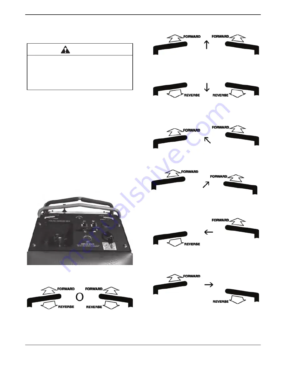
The functions of the hydrostatic motion control levers 
are:

  Forward and reverse movement.

 Steering.

  Acceleration and Deceleration.

 Stopping.

This photo shows the hydrostatic control levers are in 
the NEUTRAL position.

This is the NEUTRAL position.

This is the FORWARD travel position. The travel 
speed is dependant on how far forward the controls 
are pushed.

This is the REVERSE travel position.  The travel 
speed is dependant on how far rearward the controls 
are pulled.

For a gentle left turn, Push the right motion control 
lever further forward than the left motion control lever.

For a gentle right turn, Push the left motion control 
lever further forward than the right motion control le-
ver.

For a sharp left turn, Pull the left motion control lever 
rearward and push the right motion control lever for-
ward.

For a sharp right turn, Push the left motion control le-
ver forward and pull the right motion control lever rear-
ward.

Summary of Contents for FB2000 Series

Page 1: ...e p r o d u c t i o n FB2000 Series Commercial Debris Blower Model Description 5901811 FB2000 Series Commerical Debris Blower 5107442 Rev A Copyright Briggs Stratton Corporation Milwaukee WI USA All r...

Page 2: ...N o t f o r R e p r o d u c t i o n ferrismowers com...

Page 3: ...iders Off 7 Avoid High Pressure Fluids 7 Checking Wheel Hardware 7 Wear Appropriate Clothing 7 Maintenance and Storage 7 Prevent Fires 8 Tire Safety 8 Handling Fuel Safely 8 Handling Waste Product and...

Page 4: ...cedure 27 Impeller Removal and Inspection 28 Changing Drive Belt 28 Service Parking Brake 29 Service Motion Controls 30 Adjusting the Motion Controls 30 Adjusting Motion Controls Checking Neutral Cent...

Page 5: ...CORPORATION MILWAUKEE WI 53201 USA ASSEMBLED IN THE USA PART NO XXXXXXX SERIAL NO XXXXXXXXX PA XX SSE RT NO UKEE W MBLED I O TIO WI 5320 N T N 1 US USA A PRODUCT REFERENCE DATA Unit Model Number Unit...

Page 6: ...Symbol and Signal Words The safety alert symbol is used to identify safety information about hazards that can result in personal injury A signal word DANGER WARNING or CAUTION is used with the alert...

Page 7: ...riggs Stratton Model 386447 0403 G1 Electrical System 12 volt 16 amp alternator Battery 340 CCA CHASSIS Fuel Tank Capacity 10 gallons 38 L total Rear Wheels Tire Size 20 X 8 00 8 Inflation Pressure 22...

Page 8: ...container b Never remove gas cap or add fuel when en gine is running Do not smoke c Never refuel or drain the machine indoors Check that the operator s presence controls safety switches and shields a...

Page 9: ...ed or parked remove the key Using a Spark Arrestor The engine in this machine is equipped with a spark arrestor muffler It is a violation of California Public Resource Code Section 4442 to use or oper...

Page 10: ...not to give children a ride on the machine or in an at tachment Keep children indoors out of the work area and in the watchful eye of a responsible adult other than the operator when a machine is bein...

Page 11: ...must be tightened to specified torque using the proper procedure anytime it is loosened Wear Appropriate Clothing Always wear safety goggles or safety glasses with side shields and a hard hat when op...

Page 12: ...perform the job Always maintain the correct tire pressure DO NOT inflate the tires above the recommended pressure Never weld or heat a wheel and tire assembly The heat can cause an increase in air pr...

Page 13: ...lace fuel tank cap and tighten securely Replace all fuel container caps securely after use For gasoline engines do not use gas with metha nol Methanol is harmful to your health and to the environment...

Page 14: ...D REVERSE FORWARD REVERSE DANGER WARNING DO NOT OPERATE THIS EQUIPMENT WITHOUT PROPER AUTHORIZATION AND TRAINING IT IS THE OPERATOR S RESPONSIBILITY TO READ AND COMPLETELY UNDERSTAND ALL DANGERS WARNI...

Page 15: ...the safe and productive use of this machine Parking Brake Parking Brake Engaged This photo shows the parking brake in the EN GAGED position with all other controls in the OFF NEUTRAL position The par...

Page 16: ...com Operation Operator Station Controls Oil Alert Handle Bar Left Wheel Hydrostat Control Right Wheel Hydrostat Control Fuel Fill Fuel Cap w Gauge Ignition Key Switch Reverse Handle Bar Tach Hour Met...

Page 17: ...13 Operation Misc Controls and Checks Emergency Brake Release Lever Oil Filter Hydraulic Reservoirs Filler Fill to Bottom Line when Cold Hydro Pump Bypass Valve one on each pump Fuel Filter Air Clean...

Page 18: ...every 400 hours Hydro Gear Hydraulic Filter P N 5101026X1 Hydraulic Oil Filters One on each pump Break In Period First service at 75 hours After that every 400 hours Remove Filter Guard bolts to acce...

Page 19: ...control Result The engine must not crank Testing Emergency Parking Brake Release Emergency Brake Release Lever 1 Turn key to the ON position 2 Lift emergency brake release lever you will hear the bra...

Page 20: ...change the en gine oil The meter only runs when the engine is running and is independent of the key switch Filling Fuel Tank CAUTION Avoid injury Fuel vapors are explosive and flammable Shut engine O...

Page 21: ...erfill Clean up spilled fuel immediately 6 Re install fuel tank cap gauge Transaxle Bypass Valve IMPORTANT DO NOT push or tow machine without first engaging the transaxle bypass valve Transaxle damage...

Page 22: ...pping This photo shows the hydrostatic control levers are in the NEUTRAL position This is the NEUTRAL position This is the FORWARD travel position The travel speed is dependant on how far forward the...

Page 23: ...cause severe injury DANGER Danger rotating fan don t attempt to re move materials from intake or discharge when blower is running Engage parking brake stop engine remove key and wait until all machin...

Page 24: ...k and judge the position of the deflectors With the deflectors at about half open like the front deflector in the above photo the air stream is directed downward under the debris and is useful for blo...

Page 25: ...engine shrouds as needed x Clean behind engine shrouds and exposed fins x x Clean behind engine cooling fan screen x x Change hydraulic oil and filters x x Clean and gap spark plugs x Change fuel fil...

Page 26: ...during periods of heavy use NOTE Engine has an OIL ALERT light If there is a loss of oil pressure or oil stop engine immediately Check all oil levels If warning light stays on for more than 30 second...

Page 27: ...clockwise to remove Pull the oil filter to remove past the muffler 12 Apply a film of clean engine oil to gasket of new filter 13 Install filter Turn filter clockwise until gasket makes contact with m...

Page 28: ...ditions Refer to the engine manufacturer s owner s manual provided with your machine for the complete proce dure Replacing Fuel Filter CAUTION Avoid injury Fuel vapors are explosive and flammable Shut...

Page 29: ...rking near the engine and com ponents Check spark plugs at the intervals recommended in the Service Intervals section Refer to the engine manufacturer s owner s manual provided with your machine for t...

Page 30: ...ool 3 Jack machine up from rear Use blocking to sup port machine 4 Remove both rear tires Apply the bypass valves for both transaxles CAUTION Skid plate is heavy 5 Remove six 3 8 16 x 3 4 bolts that f...

Page 31: ...f air in the hydrostatic sys tems may be 1 Noisy operation 2 Lack of power or drive after short term opera tion 3 High operation temperature and excessive expansion of oil If starting here Follow numb...

Page 32: ...e 1 4 x 1 4 key if there is any damage to the key 7 When re installing the impeller bolt the threads must be clean of all oil must use red Loctite and torque the impeller bolt to 80 ft lbs 8 Replace s...

Page 33: ...s Engine Drive Pulley Idler Pulley Hydro Pulleys Left Right Drive Belt Routing Diagram View From the Back of the Unit 8 At this time check the battery if it needs replacing refer to Removing and Insta...

Page 34: ...16 clearance to the handle bar and tighten the jam nuts Repeat for both sides Adjusting Motion Controls Checking Neutral Center 1 Choose a hard level surface to perform this test 2 Mount the machine...

Page 35: ...he neutral plate clockwise 6 Only very small adjustments are necessary to set neutral center 7 Tighten cap screw 8 Check motion controls to ensure they return to the neutral position 9 Mount the machi...

Page 36: ...out of fork Installing 1 Slide replacement wheel into caster fork 2 Install axle bolt and locknut 3 Tighten locknut until wheel develops slight rolling resistance 4 Lower machine 5 Grease caster whee...

Page 37: ...It is poisonous and can cause serious burns Wear eye protection and gloves Keep skin protected If electrolyte is swallowed get medical attention immediately If electrolyte is splashed into eyes flush...

Page 38: ...erminals and battery cable ends with wire brush to remove corrosion Replace the terminal bolts if corroded 6 Apply battery terminal grease to the terminals and cable ends to prevent corrosion 7 Instal...

Page 39: ...nnected Spark plugs not gapped correctly Blown fuse Electrical problem dead battery Choke applied incorrectly Engine will not slow idle Carburetion problems Contact your authorized ser vice center Ben...

Page 40: ...rvice center Restricted air intake filter Other symptoms Refer to engine manufacturer s owner s manual provided with your machine for additional informa tion Electrical System Starter will not work Bl...

Page 41: ...s in a NEUTRAL position Needs motion control linkage neutral center adjust ment Machine Excessive machine vibration Engine speed too slow Increase engine rpms Drive belt not tensioned correctly Impell...

Page 42: ...pul leys 5 Apply light coat of engine oil to pivot and wear points to prevent rust 6 Check tire pressure Preparing Fuel and Engine For Storage Fuel If you have been using Stabilized Fuel add stabi liz...

Page 43: ...posts 8 Close fuel shut off valve 9 Store the battery in a cool dry place where it will not freeze NOTE The stored battery should be recharged every 90 days 10 Store the vehicle in a dry protected pla...

Page 44: ...date at the time warranty service is requested the manufacturing date of the product will be used to determine the warranty period Product registration is not required to obtain warranty service on Br...

Page 45: ...N o t f o r R e p r o d u c t i o n Notes...

Page 46: ...N o t f o r R e p r o d u c t i o n Notes...

Page 47: ...N o t f o r R e p r o d u c t i o n Notes...

Page 48: ...N o t f o r R e p r o d u c t i o n...

Reviews: