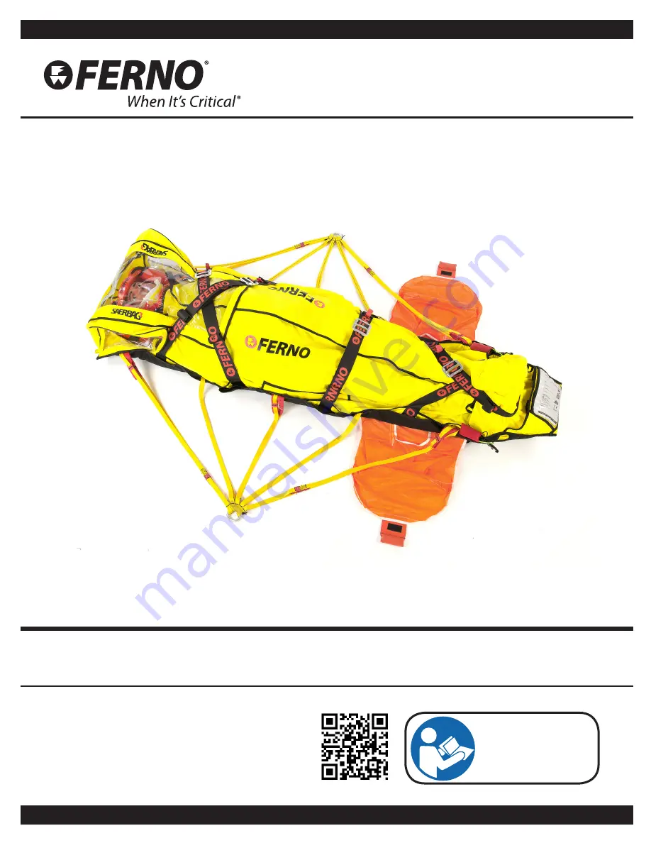
Users’ Manual
Rescue Bag for patient lifting and transport
SAERBAG III
February 2017
Pub. N° MU-094-D
Read this manual
carefully and retain
it for future reference
Page 1: ...Users Manual Rescue Bag for patient lifting and transport SAERBAG III February 2017 Pub N MU 094 D Read this manual carefully and retain it for future reference ...
Page 2: ...of this product is solely at the user s discretion Safety information is provided for the user and only ensures the minimum level necessary to avoid injury to operators and patients All other safety measures taken by the user should be within and under consideration of applicable regulations Operators must be trained before using this product Retain this manual for future reference Include the man...
Page 3: ..._______ 16 4 6 EARS anti rotation sail____________________ 17 4 7 Anti rotation tag line links _________________ 19 4 7 1 Top release systems ___________________ 19 4 8 Securing straps _________________________ 22 4 9 Lifting Handles__________________________ 22 4 10 Monitor cable access _____________________ 22 5 Using the rescue bag _________________________ 23 5 1 Before using the rescue bag___...
Page 4: ...nt to fall and be injured Always use the restraint straps as instructed in this manual Improper use of the rescue bag can cause injury Use the rescue bag only as described in this manual Before any rescue operation ensure that the load is evenly distributed on the Saerbag lifting bridle arms Untrained helpers may cause damage and or injury or hurt themselves Do not allow untrained helpers to prepa...
Page 5: ...ly To request new labels contact Ferno Washington Italia Customer Service page 2 The label shown below is applied to the rescue bag Main Label 1 6 Symbol Glossary The following symbols are present in this manual and or on the rescue bag label The rescue bag and this manual both carry the CE marking Read the Users Manual carefully This product meets European Union Standards Load capacity in kilos a...
Page 6: ... Ferno Millennia backboard or a Ferno vacuum mattress and to be rescued using a winch and or ropes in a difficult environment thanks to its special integrated lifting bridle It can be used for rescue with a winch from a rotary wing aircraft according to the winch use procedures The rescue bag has 4 adjustable straps to correctly immobilize the patient The two upper torso straps must be crossed the...
Page 7: ...ral anti rotation sail 2 Foot strap Anti rotation tag line links 6 Integrated lifting bridle with central lifting rings 2 Monitor cable access Lateral red lifting handles 2 Mylar cover Straps to secure the immobilization device 6 Length Adjustment System 2 Velcro fastening at head side 2 Velcro fastening at foot side Patient body Velcro fastening HEAD SIDE FOOT SIDE ...
Page 8: ...has been exceeded see paragraph 6 4 Inspection page 28 WARNING Untrained operators may injure themselves and or cause damage or injury Only trained qualified operators should be allowed to use the SAERBAG WARNING Do not exceed the load limit of the rescue bag shown in this manual To request additional free users manuals contact Ferno Washington Italia Customer Relations page 2 USERS AND MAINTENANC...
Page 9: ...nal length adjustment system Figure 2 Inserting the head area Figure 3 Inserting the foot area ADJUSTING THE LENGTH To adjust the rescue bag length 1 Place the immobilization device in the rescue bag First insert the head area Figure 2 then the foot area Figure 3 of the SCOOPEXL stretcher backboard 2 After having placed the immobilization device in the rescue bag correctly pull the inner straps on...
Page 10: ...ENGTHENING THE RESCUE BAG To open the rescue bag to its original length pull the buckles of the inner straps on the right and left in the opposite direction towards the foot area of the rescue bag Figure 6 Using the straps SECURING THE STRAPS Each strap has two buckles a large one and a small one Figure 7 To secure the straps 1 Take the small buckle in one hand and the large one in the other Figur...
Page 11: ...raps are correctly adjusted and do not constrict the patient before any operation Figure 11 Adjusting the straps UNDOING THE STRAPS To undo the straps 1 Lift the small buckle Figure 12 2 Unhook the small buckle by passing it through the large buckle Figure 13 Figure 12 Lifting the small buckle Figure 13 Unhooking the small buckle Important Before rescue ensure that any excess strap length has been...
Page 12: ...s in Securing the straps page 10 Torso straps are positioned so that they can be crossed easily by the operator Torso straps are numbered in this manual to make application easier Figure 14 They are numbered clockwise from the operator s point of view 3 Place the small buckle of the second torso strap on the left of the rescue bag 4 Figure 14 in the large buckle of the second torso strap on the ri...
Page 13: ...uctions in Securing the straps page 10 3 Adjust the straps Figure 19 4 Tuck in the excess of the straps using the integrated elastics Ensure that any excess strap length has been secured in order not to hamper rescue operations Ensure that the straps are applied correctly so that the patient is secure inside the rescue bag Figure 19 Adjusting the straps Figure 20 Leg strap correctly applied Figure...
Page 14: ...25 To adjust the straps see Adjusting the straps page 11 8 Tuck in the excess of the straps using the integrated elastics Ensure that any excess strap length has been secured in order not to hamper rescue operations Ensure that all the straps are applied correctly so that the patient is secure inside the rescue bag Figure 25 Adjusting the foot strap Figure 26 Foot strap correctly applied Important...
Page 15: ...e bag has an integrated lifting bridle Figure 29 The lifting bridle has 10 arms 5 per side and two central lifting rings that karabiners must be attached to before any rescue operation It has a shortening system with 4 integrated red loops on the outer arms of the lifting bridle on the right and left that ensure correct load distribution if the rescue bag has been shortened to adapt it to the leng...
Page 16: ...ng bridle shortening system Shown by the arrows red loops To shorten the lifting bridle 1 Use the red loops sewn on the outer arms of the lifting bridle Figure 30 2 Place correctly sized karabiners in the loops Figure 31 3 Attach both karabiners to the central ring Figure 31 4 Carry out the same operation on the lifting bridle arms on the opposite side Figure 32A Use the loops of the lifting bridl...
Page 17: ...ndle outside the pocket Always leave the handle visible and easily reachable for the operator by fastening it with Velcro to the outside of the pocket Figure 33 EARS anti rotation sails TAKING OUT THE SAIL 1 Hold the orange handle Figure 34 2 Pull the handle outwards so the sail comes out completely Figure 35 Figure 34 EARS anti rotation sail handle Figure 35 Taking out the EARS anti rotation sail...
Page 18: ...he Velcro 4 Close the pocket with the Velcro fastening leaving the handle outside Figure 39 Figure 39 Closing the pocket Keep the two EARS sails in the pockets when not in use 37A 37B 38A 38B Technical Rescue Technical Rescue procedures require special skills and are potentially hazardous activities No rescue personnel should attempt technical rescue procedures unless they have received profession...
Page 19: ... after the EARS sails on both sides of the rescue bag They have a red handle Each system has Figure 41 1 a red handle 2 a green string 3 a strap with two differently sized rings a small one and a large one sewn on an eyelet in the strap a white loop Prepare the top release system before use PREPARING THE SYSTEM 1 Position the connector between the two rings sewn onto the strap Figure 42 2 Flip the...
Page 20: ...Replacing the green string in the pocket 5 Take the green string and place it in the loop coming out at the back of the strap Figure 46 6 Replace the green string in its pocket Figure 47 Check that each step has been carried out correctly and that the system is ready for use After having prepared the system check that it will hold To check that it will hold pull the connector from the opposite par...
Page 21: ...oint of the rescue phase the operator decides to release the tag line proceed as follows 1 Hold the red handle Figure 49 2 Pull the red handle Figure 50 Figure 51 String pulled out Figure 52 Connector undone from the tag line 3 By pulling the handle the green string comes out of its pocket Figure 51 and the white loop is freed so that the connector can be undone from the tag line Figure 52 ...
Page 22: ...etcher 3 Fasten both sides of the strap with Velcro so that the strap fits firmly around the stretcher handle Ensure you have correctly applied the straps to the immobilization device for greater internal stability 4 9 Lifting Handles The rescue bag has 6 red lifting handles in the head center and foot area Hold the lifting handles to lift the rescue bag if needed Figure 54 Only lift loads that yo...
Page 23: ... can be used for a range of circumstances and scenarios It is the responsibility of trained Emergency Service personnel to evaluate the patient s conditions and determine the most suitable equipment and procedures Always follow guidelines and local medical protocols Always attend to the patient and never leave him alone when using the rescue bag Technical rescue operators must have received adequa...
Page 24: ...ing the head area Figure 59 Inserting the foot area 4 Adjust the length of the rescue bag correctly using the internal length adjustment system in order to hold the stretcher and avoid it slipping out during rescue operations Ensure the rescue bag is adjusted so that it perfectly fits the immobilization device To adjust the length see paragraph 4 1 Length Adjustment page 9 5 Use the 6 internal str...
Page 25: ...plied and adjusted correctly and that the load distribution on the lifting bridle arms is correct If you have to use the lifting bridle shortening system to correctly distribute the load make sure you use the red loops To use the lifting bridle shortening system see paragraph 4 5 1 Lifting bridle shortening system page 16 12 When you have checked everything made adjustments and checked that the lo...
Page 26: ...h right 4 When the rescue bag has been properly prepared the patient is correctly secured and all checks have been carried out the patient can be lifted During lifting the patient will automatically be in a sitting position 5 5Rescuingthepatientfromarockface If the patient is rescued from a rock face the rescue bag must be prepared beforehand Ensure that the patient immobilization device has been ...
Page 27: ...useseriousdamage or injury Carry out maintenance as described in this manual 6 1 Routine Maintenance The sheet requires regular maintenance Ferno recommends routine maintenance every two years The Ferno technical staff will issue a certificate of conformity for the device after maintenance The table on the right shows the minimum maintenance schedule The lifting bridle arms and central lifting rin...
Page 28: ...ree from cuts or worn edges Is the stitching undone or breaking Are the securing straps inside the rescue bag Are the loops and securing straps in good condition with no cuts or worn edges Does the Velcro on every strap work properly Are there any visible signs of damage on the rescue bag or its components 6 4 Inspection To guarantee optimal use of the rescue bag all components must be in good con...
Page 29: ... follows Figure 62 Carrying case Flying Rescue bag III REPLACING THE RESCUE BAG 1 Put the rescue bag on the floor and place the straps and lifting bridle inside the rescue bag Figure 63 2 Fold the two sides of the rescue bag inwards Figure 64 Figure 63 Place the straps and the lifting bridle inside Figure 64 Close the sides Figure 65 Placing the rescue bag in the carrying case Figure 66 Fastening ...
Page 30: ...67 6 Close the carrying case The Flying Rescue bag III carrying case has another compartment at the back to store the SCOOPEXL stretcher together with the rescue bag Place the SCOOPEXL stretcher in two parts in its compartment Figure 68 Figure 67 Folding the rescue bag Figure 68 SCOOPEXL storage compartment Maintenance Figure 69 KIT FLYING III Y ...
Page 31: ...reephone 800 501 711 Telephone 39 051 686 00 28 Fax 39 051 686 15 08 E mail info ferno it Internet www ferno it For information on the correct use of the SAERBAG III and to organize training courses on the correct use of the device contact Ferno Washington Italia Customer Relations 7 1 SAERBAG III Accessories Description Code Holdall yellow BAG SAERBAG III Y Holdall military version BAG SAERBAG II...
Page 32: ... that do not have the original Ferno trademark sold by Ferno W Italia s r l are covered by the product manufacturer s original warranty Ferno W Italia s r l will not extend a warranty beyond the product manufacturer s warranty period Ferno W Italia s r l will not be held responsible for products manufactured by others The warranty will not apply in the case of failure to observe instructions for u...
Page 33: ...ons that do not derive from defects of conformity will only be accepted after they have been checked by specialized Ferno W Italia s r l staff 9 6 Life Cycle The Saerbag 3 has a life cycle of 10 years after which time our technical staff will assess the state of the device and confirm its conformity or otherwise 9 4 Complaints Any complaints must be communicated to the vendor or to Ferno W Italia ...
Page 34: ...34 Ferno Washington Italia MU 094 D February 2017 SAERBAG III TRAINING RECORD Date Instructor s name Type of Training ...
Page 35: ...35 Ferno Washington Italia MU 094 D February 2017 SAERBAG III MAINTENANCE RECORD Date Type of Maintenance Maintenance Technician ...
Page 36: ... Pieve di Cento BO ITALY Telephone Freephone 800 501 711 Telephone 39 051 686 00 28 Fax 39 051 686 15 08 E mail info ferno it Internet www ferno it Product users and maintenance manual needed for the safe operation efficiency and reliability of the product and to render warranty conditions valid January 2017 Pub N MU 094 D ...