Fer FERtech F 32 D Instructions For Use, Installation And Maintenance Download Page 17

FERtech F 24 D - F 32 D

17

EN

4.3 Maintenance
Periodical check

To ensure correct operation of the unit over time, have qualified personnel carry out a
yearly check, providing for the following:

The control and safety devices (gas valve, flow meter, thermostats, etc.) must func-
tion correctly.

The fume exhaust circuit must be perfectly efficient.
(Sealed chamber boiler: fan, pressure switch, etc. -The sealed chamber must be
tight: seals, cable glands, etc.)
(Open chamber boiler: anti-backflow device, fume thermostat, etc.)

The air-fume end piece and ducts must be free of obstructions and leaks

The burner and exchanger must be clean and free of deposits. For possible cleaning
do not use chemical products or wire brushes.

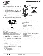
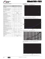
The electrode must be properly positioned and free of scale.

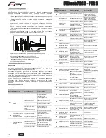
fig. 17 - Electrode positioning

The gas and water systems must be airtight.

The water pressure in the cold water system must be about 1 bar; otherwise, bring
it to that value.

The circulating pump must not be blocked.

The expansion tank must be filled.

The gas flow and pressure must correspond to that given in the respective tables.

4.4 Troubleshooting
Diagnostics

The boiler is equipped with an advanced self-diagnosis system. In case of a boiler fault,
the display will flash together with the fault symbol (detail 11 - fig. 1) indicating the fault
code.
There are faults that cause permanent shutdown (marked with the letter "

A

"): to restore

operation, press the RESET button (detail 6 - fig. 1) for 1 second or RESET on the op-
tional remote timer control if installed; if the boiler fails to start, it is necessary to eliminate
the fault.
Faults marked with the letter "

F

" cause temporary shutdowns that are automatically reset

as soon as the value returns within the boiler's normal working range.

List of faults

Table. 8

Code

fault

Fault

Possible cause

Cure

      A01

No burner ignition

No gas

Check the regular gas flow to the 
boiler and that the air has been 
eliminated from the pipes

Ignition/detection electrode fault

Check the wiring of the electrode and 
that it is correctly positioned and free 
of any deposits

Faulty gas valve

Check the gas valve and replace it if 
necessary

Gas valve wiring disconnected

Check the wiring

Ignition power too low

Adjust the ignition power

A02

Flame present signal with 
burner off

Electrode fault

Check the ionisation electrode wiring

Card fault

Check the card

A03

Overtemperature protec-
tion activation

Heating sensor damaged

Check the correct positioning and 
operation of the heating sensor

No water circulation in the system Check the circulating pump
Air in the system

Vent the system

F04

Card parameter fault

Wrong card parameter setting

Check the card parameter and modify 
it if necessary

F05

Card parameter fault

Wrong card parameter setting

Check the card parameter and modify 
it if necessary

Fan fault

Wiring disconnected

Check the wiring

Defective fan

Check the fan

Card fault

Check the card

A06

No flame after the ignition 
phase

Low pressure in the gas system

Check the gas pressure

Burner minimum pressure setting Check the pressures

F07

Card parameter fault

Wrong card parameter setting

Check the card parameter and modify 
it if necessary

A09

Gas valve fault

Wiring disconnected

Check the wiring

Faulty gas valve

Check the gas valve and replace it if 
necessary

±

 0,5

=

=

F10

Delivery sensor 1 fault

Sensor damaged

Check the wiring or replace the 
sensor

Wiring shorted
Wiring disconnected

F11

DHW sensor fault

Sensor damaged

Check the wiring or replace the 
sensor

Wiring shorted
Wiring disconnected

F14

Delivery sensor 2 fault

Sensor damaged

Check the wiring or replace the 
sensor

Wiring shorted
Wiring disconnected

A16

Gas valve fault

Wiring disconnected

Check the wiring

Faulty gas valve

Check the gas valve and replace it if 
necessary

F20

Combustion control fault

Fan fault

Check the fan and fan wiring

Faulty baffle

Check the baffle and replace it if nec-
essary

Flue not correctly sized or 
obstructed

Check the flue

A21

Poor combustion fault

Fault F20 generated 6 times in the 
last 10 minutes

See fault F20

A23

Card parameter fault

Wrong card parameter setting

Check the card parameter and modify 
it if necessary

A24

Card parameter fault

Wrong card parameter setting

Check the card parameter and modify 
it if necessary

F34

Supply voltage under 180V. Electric mains trouble

Check the electrical system

F35

Faulty mains frequency

Electric mains trouble

Check the electrical system

F37

Incorrect system water 
pressure

Pressure too low

Fill the system

Water pressure switch damaged 
or not connected

Check the sensor

F39

External probe fault

Probe damaged or wiring shorted

Check the wiring or replace the 
sensor

Probe disconnected after activat-
ing the sliding temperature

Reconnect the external sensor or 
disable the sliding temperature

A41

Sensor positioning

Delivery sensor or DHW sensor 
detached from the pipe

Check the correct positioning and 
operation of the sensors

F42

Heating sensor fault

Sensor damaged

Replace the sensor

F43

Exchanger protection trips.

No H

2

O system circulation

Check the circulating pump

Air in the system

Vent the system

F50

Gas valve fault

Modulating Operator wiring 
disconnected

Check the wiring

Faulty gas valve

Check the gas valve and replace it if 
necessary

A51

Poor combustion fault

Inlet/exhaust flue obstruction

Check the flue

Code

fault

Fault

Possible cause

Cure

cod. 354

%

581

  -  Rev. 0

3

 - 

/201

5

Summary of Contents for FERtech F 32 D

Page 1: ...80 80 5 51 54 76 58 5 178 126 A B C D E F 330 110 120 120 725 5 676 5 50 76 54 51 80 5 74 5 93 114 30 30 24 5 24 5 24 5 F A B C D E 85 115 115 85 195 330 A B C D E F IT ISTRUZIONE PER L USO L INSTALLA...

Page 2: ...selezione modalit Estate Inverno Men Temperatura Scorrevole 7 Tasto selezione modalit Economy Comfort on off apparecchio 8 Simbolo acqua calda sanitaria 9 Indicazione funzionamento sanitario 10 Indica...

Page 3: ...di compensazione Regolazioni da Cronocomando Remoto A Se alla caldaia collegato il Cronocomando Remoto opzionale le regolazioni descritte in precedenza vengono gestite secondo quanto riportato nella t...

Page 4: ...e essere sostituito dall utente In caso di danneggiamento del cavo spegnere l apparecchio e per la sua so stituzione rivolgersi esclusivamente a personale professionalmente qualifica to In caso di sos...

Page 5: ...ertificati separatamente EN 1856 1 B2X Aspirazione dal locale di installazione e scarico a parete o tetto IMPORTANTE IL LOCALE DEVE ESSERE DOTATO DI VENTILAZIONE APPROPRIATA FERtech F 24 D FERtech F 3...

Page 6: ...menti decrementi di 1 o 2 unit del parametro q02 attraverso la pressione dei tasti sanitario dopo ogni modifica il valore viene memorizzato atten dere 10 secondi affinch la pressione si stabilizzi Pre...

Page 7: ...ione parametro scheda Verificare ed eventualmente modificare il parametro scheda F05 Anomalia parametri scheda Errata impostazione parametro scheda Verificare ed eventualmente modificare il parametro...

Page 8: ...sanitaria 44 Valvola gas 10 Mandata impianto 56 Vaso di espansione 11 Ritorno impianto 72 Termostato ambiente non fornito 14 Valvola di sicurezza 74 Rubinetto di riempimento impianto 16 Ventilatore 81...

Page 9: ...3 h 0 88 1 22 Ugelli bruciatore G31 n x 11 x 0 79 15 x 0 79 Pressione gas alimentazione G31 mbar 37 37 Pressione gas max al bruciatore G31 mbar 35 0 35 0 Pressione gas min al bruciatore G31 mbar 5 0 5...

Page 10: ...cuito elettrico A Attenzione Prima di collegare il termostato ambiente o il cronocomando re moto togliere il ponticello sulla morsettiera 81 1kW L N 230V 50 Hz 16 N L 32 L N T T 278 T 42 4 3 2 1 44 38...

Page 11: ...rtatenelpresenteCer cato Gliinterven ingaranzianon modi cano la data di decorrenza della garanzia e non prolungano la durata della stessa Esclusioni Sono esclusi dalla presente garanzia i dife di conf...

Page 12: ...Comfort mode selection button 8 DHW symbol 9 DHW mode 10 Summer mode 11 Multifunction 12 Eco Economy mode 13 Heating 14 Heating symbol 15 Burner lit and actual power level flashing during combustion...

Page 13: ...s from Remote Timer Control A If the Remote Timer Control optional is connected to the boiler the above ad justments are managed according to that given in table 1 Table 1 System water pressure adjust...

Page 14: ...replaced by the user if damaged switch the unit off and have the cable replaced by professionally qualified personnel If replacing the power cable only use HAR H05 VV F 3x0 75 mm2 cable with max ext...

Page 15: ...d pipes EN 1856 1 B2X Intake from installation room and wall or roof exhaust IMPORTANT THE ROOM MUST BE PROVIDED WITH APPROPRIATE VENTILATION FERtech F 24 D FERtech F 32 D Max permissible length 60 me...

Page 16: ...pressure pro ceed by increases decreases of 1 or 2 units of parameter q02 by pressing the DHW buttons the value is stored after each modification wait 10 seconds for the pressure to stabilise Press t...

Page 17: ...em F04 Card parameter fault Wrong card parameter setting Check the card parameter and modify it if necessary F05 Card parameter fault Wrong card parameter setting Check the card parameter and modify i...

Page 18: ...perature sensor 9 Cold water inlet 44 Gas valve 10 System delivery 56 Expansion tank 11 System return 72 Room thermostat not supplied 14 Safety valve 74 System filling cock 16 Fan 81 Ignition and dete...

Page 19: ...in gas delivery G20 m3 h 0 88 1 22 Burner nozzles G31 no x 11 x 0 79 15 x 0 79 Gas supply pressure G31 mbar 37 37 Max gas pressure at burner G31 mbar 35 0 35 0 Min gas pressure at burner G31 mbar 5 0...

Page 20: ...ectrical circuit A Important Before connecting the room thermostat or the remote timer FRQtrol remove the jumper on the terminal block 81 1kW L N 230V 50 Hz 16 N L 32 L N T T 278 T 42 4 3 2 1 44 38 11...

Page 21: ...10 11 12 Eco 13 14 15 16 17 13 1 11 1 d2 9 1 11 1 d1 Comfort omfort 9 1 11 1 cap 4 4 11 1 d3 d4 2 3 5 7 1 5 2 7 1 5 3 B sez 3 3 2 4 6 1 2 10 1 6 1 2 3 4 1 30 C 85 C 45 C 4 reset eco comfort 4 13 11 1...

Page 22: ...1 1 1 10 0 3 1 OF 1 1 6 5 6 1 6 A 1 1 17 1 1 0 F37 1 7 7 3 3 1 3 2 2009 142 EN 297 pr A6 5 C A IIIIIII I I I I I I I I I I I I I 20 30 40 50 60 70 80 90 85 20 10 0 10 20 1 2 3 4 5 6 8 9 10 7 20 10 0...

Page 23: ...A B 9 2 10 3 1 2 3 4 5 6 72 139 138 3 4 C1X C3X 60 100 80 125 5 10 90 1 0 5 45 0 5 0 25 0 2 FERtech F 24 D 43 FERtech F 32 D 45 0 3 FERtech F 24 D 43 FERtech F 32 D 45 2 5 3 10 A 1 1 2 2 4 3 3 5 6 B...

Page 24: ...1KWMA06K 2 0 2 0 4 0 45 1KWMA01K 1 2 2 2 45 1KWMA65A 1 2 2 2 90 1KWMA02K 2 0 3 0 90 1KWMA82A 1 5 2 5 90 1KWMA70U 1 5 2 5 1KWMA16U 0 2 0 2 1KWMA55U 3 0 T 1KWMA05K 7 0 1KWMA85A 2 0 1KWMA86A 5 0 80 80 1...

Page 25: ...0 2 1 100 TEST TEST TEST 3 4 1 5 TEST 15 B TEST cap 4 1 Eco Comfort 2 q02 q02 1 2 10 3 1 q01 q01 1 2 10 Eco Comfort 2 TEST TEST cap 4 1 TEST sez 4 1 3 1 00 100 5 TEST sez 4 1 4 2 cap 5 III I I I I I I...

Page 26: ...D F 32 D 26 RU 4 3 17 1 4 4 11 1 A RESET 6 1 1 RESET F 8 A01 A02 A03 3 0 5 F04 F05 A06 F07 A09 F10 1 F11 F14 2 A16 F20 A21 F20 10 F20 A23 A24 F34 180 F35 F37 F39 A41 F42 F43 H2 O F50 A51 cod 354 581...

Page 27: ...10 8 7 9 11 194 39 74 187 22 44 32 114 36 14 19 27 28 29 5 16 81 95 278 42 38 37 10 7 11 194 39 74 187 22 56 8 9 5 38 7 39 8 42 9 44 10 56 11 72 14 74 16 81 19 95 22 114 27 138 28 139 29 187 32 194 3...

Page 28: ...3 0 88 1 22 G31 x 11 x 0 79 15 x 0 79 G31 37 37 G31 35 0 35 0 G31 5 0 5 0 G31 2 00 2 69 G31 0 65 0 90 3 3 PMS 0 8 0 8 C 90 90 tmax 1 0 1 2 8 10 1 1 9 9 PMW 0 25 0 25 t 25 C 13 7 18 3 t 30 C 11 4 15 2...

Page 29: ...FERtech F 24 D F 32 D 29 RU 5 5 22 A 81 1kW L N 230V 50 Hz 16 N L 32 L N T T 278 T 42 4 3 2 1 44 38 114 ABM01 LC32 3 2 1 95 72 139 138 cod 354 581 Rev 03 2015...

Page 30: ...tromagnetica Presidente e Legale rappresentante Cav del Lavoro Dante Ferroli IT Declaration of conformity Manufacturer declares that this unit complies with the following EU directives Gas Appliance D...

Page 31: ......

Page 32: ...Ferroli spa 37047 San Bonifacio Verona Italy Via Ritonda 78 A tel 39 045 6139411 fax 39 045 6100933 www industriefer it...

Reviews: