background image

FERtech F 24 D - F 32 D

14

EN

3.3 Plumbing connections
Important

B

The safety valve outlet must be connected to a funnel or collection pipe to pre-
vent water spurting onto the floor in case of overpressure in the heating circuit.
Otherwise, if the discharge valve cuts in and floods the room, the boiler manu-
facturer cannot be held liable.

B

Before making the connection, check that the unit is arranged for operation with
the type of fuel available and carefully clean all the system pipes.

Carry out the relevant connections according to the cover diagram and the symbols giv-
en on the unit.

Note:

 The unit has an internal bypass in the heating circuit.

Water system characteristics

In the presence of water harder than 25° Fr (1°F = 10ppm CaCO

3

), use suitably treated

water in order to avoid possible scaling in the boiler.

Antifreeze system, antifreeze fluids, additives and inhibitors

When necessary, antifreeze fluids, additives and inhibitors can be used only if the man-
ufacturer of such fluids or additives guarantees that they are suitable and do not cause
damage to the exchanger or other components and/or materials of the boiler and system.
Do not use generic antifreeze fluids, additives or inhibitors that are not specific for use in
heating systems and compatible with the materials of the boiler and system.

3.4 Gas connection

The gas must be connected to the relevant union (see figure on cover) in conformity with
the current regulations, with a rigid metal pipe or with a continuous surface flexible s/steel
tube, installing a gas cock between the system and boiler. Make sure all the gas connec-
tions are tight.

3.5 Electrical connections
Important

B

The unit must be connected to an efficient earthing system in conformity with
current safety regulations. Have the efficiency and suitability of the earthing
system checked by professionally qualified personnel; the Manufacturer de-
clines any liability for damage caused by failure to earth the system.
The boiler is prewired and provided with a "Y" type cable (without plug) for con-
nection to the electric line. The connections to the power supply must be per-
manent and equipped with a double-pole switch with contact opening distance
of at least 3 mm, installing fuses of max. 3A between the boiler and the line.
Make sure to respect the polarities (LINE: brown wire / NEUTRAL: blue wire /
EARTH: yellow/green wire) in connections to the electric line.

B

The unit's power cable must not be replaced by the user; if damaged, switch
the unit off and have the cable replaced by professionally qualified personnel.
If replacing the power cable, only use 

"HAR H05 VV-F"

 3x0.75 mm2 cable with

max. ext. diameter of 8 mm.

Room thermostat (optional)

B

IMPORTANT: THE ROOM THERMOSTAT MUST HAVE VOLTAGE-FREE
CONTACTS. CONNECTING 230 V TO THE ROOM THERMOSTAT TERMI-
NALS WILL PERMANENTLY DAMAGE THE ELECTRONIC BOARD.
When connecting time controls or a timer, do not take the power supply for
these devices from their breaking contacts Their power supply must be by
means of direct connection from the mains or with batteries, depending on the
kind of device.

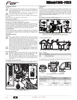
Accessing the electrical terminal block

The electrical terminal block can be accessed after removing the casing. The layout of
the terminals for the various connections is also given in the wiring diagram in fig. 22.

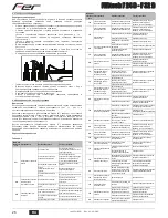
fig. 8 - Accessing the terminal block

3.6 Fume ducts
Important

The unit is a "C type" with sealed chamber and forced draught, the air inlet and fume out-
let must be connected to one of the following extraction/suction systems. The unit is ap-
proved for operation with all the 

Cny

 flue configurations given on the dataplate. Some

configurations may be expressly limited or not permitted by law, standards or local reg-
ulations. Before installation, check and carefully follow the instructions. Also, comply with
the instructions on the positioning of wall and/or roof terminals and the minimum distanc-
es from windows, walls, ventilation openings, etc.

Baffles

Boiler operation requires fitting the baffles supplied with the unit. Check that the boiler
has right baffle (if to be used) and its correct positioning.

A

 Baffle replacement with 

boiler not installed

B

 Baffle replacement with 

boiler and fume ducts already installed

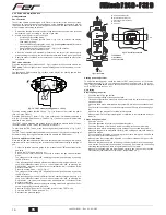
Connection with coaxial pipes

fig. 9 - Examples of connection with coaxial pipes (

 = Air / 

 = Fumes)

Table. 2 - Typology

For coaxial connection, fit the unit with one of the following starting accessories. For the
wall hole dimensions, refer to the figure on the cover.

fig. 10 - Starting accessory for coaxial ducts

Table. 3 - Baffles for coaxial ducts

1

2 3 4

5 6

72

139

138

3

4

Type

Description

C1X

Wall horizontal exhaust and inlet

C3X

Roof vertical exhaust and inlet

Coaxial 60/100

Coaxial 80/125

Max. permissible length

5 m

10 m

Reduction factor 90° bend

1 m

0.5 m

Reduction factor 45° bend

0.5 m

0.25 m

Baffle to use

0 ÷ 2 m

FERtech F 24 D

 = Ø 43

FERtech F 32 D

 = Ø 45

0 ÷ 3 m

FERtech F 24 D

 = Ø 43

FERtech F 32 D

 = Ø 45

2 ÷ 5 m

no baffle

3 ÷ 10 m

no baffle

A

1

1

2

2

4

3

3

5

6

B

C

1X

C

1X

C

3X

C

3X

C

3X

C

1X

Ø126

Ø82

Ø60

Ø130

Ø

100

010018X0

010006X0

010007X0

68

11

8

100

60

45.6

100

60

cod. 354

%

581

  -  Rev. 0

3

 - 

/201

5

Summary of Contents for FERtech F 32 D

Page 1: ...80 80 5 51 54 76 58 5 178 126 A B C D E F 330 110 120 120 725 5 676 5 50 76 54 51 80 5 74 5 93 114 30 30 24 5 24 5 24 5 F A B C D E 85 115 115 85 195 330 A B C D E F IT ISTRUZIONE PER L USO L INSTALLA...

Page 2: ...selezione modalit Estate Inverno Men Temperatura Scorrevole 7 Tasto selezione modalit Economy Comfort on off apparecchio 8 Simbolo acqua calda sanitaria 9 Indicazione funzionamento sanitario 10 Indica...

Page 3: ...di compensazione Regolazioni da Cronocomando Remoto A Se alla caldaia collegato il Cronocomando Remoto opzionale le regolazioni descritte in precedenza vengono gestite secondo quanto riportato nella t...

Page 4: ...e essere sostituito dall utente In caso di danneggiamento del cavo spegnere l apparecchio e per la sua so stituzione rivolgersi esclusivamente a personale professionalmente qualifica to In caso di sos...

Page 5: ...ertificati separatamente EN 1856 1 B2X Aspirazione dal locale di installazione e scarico a parete o tetto IMPORTANTE IL LOCALE DEVE ESSERE DOTATO DI VENTILAZIONE APPROPRIATA FERtech F 24 D FERtech F 3...

Page 6: ...menti decrementi di 1 o 2 unit del parametro q02 attraverso la pressione dei tasti sanitario dopo ogni modifica il valore viene memorizzato atten dere 10 secondi affinch la pressione si stabilizzi Pre...

Page 7: ...ione parametro scheda Verificare ed eventualmente modificare il parametro scheda F05 Anomalia parametri scheda Errata impostazione parametro scheda Verificare ed eventualmente modificare il parametro...

Page 8: ...sanitaria 44 Valvola gas 10 Mandata impianto 56 Vaso di espansione 11 Ritorno impianto 72 Termostato ambiente non fornito 14 Valvola di sicurezza 74 Rubinetto di riempimento impianto 16 Ventilatore 81...

Page 9: ...3 h 0 88 1 22 Ugelli bruciatore G31 n x 11 x 0 79 15 x 0 79 Pressione gas alimentazione G31 mbar 37 37 Pressione gas max al bruciatore G31 mbar 35 0 35 0 Pressione gas min al bruciatore G31 mbar 5 0 5...

Page 10: ...cuito elettrico A Attenzione Prima di collegare il termostato ambiente o il cronocomando re moto togliere il ponticello sulla morsettiera 81 1kW L N 230V 50 Hz 16 N L 32 L N T T 278 T 42 4 3 2 1 44 38...

Page 11: ...rtatenelpresenteCer cato Gliinterven ingaranzianon modi cano la data di decorrenza della garanzia e non prolungano la durata della stessa Esclusioni Sono esclusi dalla presente garanzia i dife di conf...

Page 12: ...Comfort mode selection button 8 DHW symbol 9 DHW mode 10 Summer mode 11 Multifunction 12 Eco Economy mode 13 Heating 14 Heating symbol 15 Burner lit and actual power level flashing during combustion...

Page 13: ...s from Remote Timer Control A If the Remote Timer Control optional is connected to the boiler the above ad justments are managed according to that given in table 1 Table 1 System water pressure adjust...

Page 14: ...replaced by the user if damaged switch the unit off and have the cable replaced by professionally qualified personnel If replacing the power cable only use HAR H05 VV F 3x0 75 mm2 cable with max ext...

Page 15: ...d pipes EN 1856 1 B2X Intake from installation room and wall or roof exhaust IMPORTANT THE ROOM MUST BE PROVIDED WITH APPROPRIATE VENTILATION FERtech F 24 D FERtech F 32 D Max permissible length 60 me...

Page 16: ...pressure pro ceed by increases decreases of 1 or 2 units of parameter q02 by pressing the DHW buttons the value is stored after each modification wait 10 seconds for the pressure to stabilise Press t...

Page 17: ...em F04 Card parameter fault Wrong card parameter setting Check the card parameter and modify it if necessary F05 Card parameter fault Wrong card parameter setting Check the card parameter and modify i...

Page 18: ...perature sensor 9 Cold water inlet 44 Gas valve 10 System delivery 56 Expansion tank 11 System return 72 Room thermostat not supplied 14 Safety valve 74 System filling cock 16 Fan 81 Ignition and dete...

Page 19: ...in gas delivery G20 m3 h 0 88 1 22 Burner nozzles G31 no x 11 x 0 79 15 x 0 79 Gas supply pressure G31 mbar 37 37 Max gas pressure at burner G31 mbar 35 0 35 0 Min gas pressure at burner G31 mbar 5 0...

Page 20: ...ectrical circuit A Important Before connecting the room thermostat or the remote timer FRQtrol remove the jumper on the terminal block 81 1kW L N 230V 50 Hz 16 N L 32 L N T T 278 T 42 4 3 2 1 44 38 11...

Page 21: ...10 11 12 Eco 13 14 15 16 17 13 1 11 1 d2 9 1 11 1 d1 Comfort omfort 9 1 11 1 cap 4 4 11 1 d3 d4 2 3 5 7 1 5 2 7 1 5 3 B sez 3 3 2 4 6 1 2 10 1 6 1 2 3 4 1 30 C 85 C 45 C 4 reset eco comfort 4 13 11 1...

Page 22: ...1 1 1 10 0 3 1 OF 1 1 6 5 6 1 6 A 1 1 17 1 1 0 F37 1 7 7 3 3 1 3 2 2009 142 EN 297 pr A6 5 C A IIIIIII I I I I I I I I I I I I I 20 30 40 50 60 70 80 90 85 20 10 0 10 20 1 2 3 4 5 6 8 9 10 7 20 10 0...

Page 23: ...A B 9 2 10 3 1 2 3 4 5 6 72 139 138 3 4 C1X C3X 60 100 80 125 5 10 90 1 0 5 45 0 5 0 25 0 2 FERtech F 24 D 43 FERtech F 32 D 45 0 3 FERtech F 24 D 43 FERtech F 32 D 45 2 5 3 10 A 1 1 2 2 4 3 3 5 6 B...

Page 24: ...1KWMA06K 2 0 2 0 4 0 45 1KWMA01K 1 2 2 2 45 1KWMA65A 1 2 2 2 90 1KWMA02K 2 0 3 0 90 1KWMA82A 1 5 2 5 90 1KWMA70U 1 5 2 5 1KWMA16U 0 2 0 2 1KWMA55U 3 0 T 1KWMA05K 7 0 1KWMA85A 2 0 1KWMA86A 5 0 80 80 1...

Page 25: ...0 2 1 100 TEST TEST TEST 3 4 1 5 TEST 15 B TEST cap 4 1 Eco Comfort 2 q02 q02 1 2 10 3 1 q01 q01 1 2 10 Eco Comfort 2 TEST TEST cap 4 1 TEST sez 4 1 3 1 00 100 5 TEST sez 4 1 4 2 cap 5 III I I I I I I...

Page 26: ...D F 32 D 26 RU 4 3 17 1 4 4 11 1 A RESET 6 1 1 RESET F 8 A01 A02 A03 3 0 5 F04 F05 A06 F07 A09 F10 1 F11 F14 2 A16 F20 A21 F20 10 F20 A23 A24 F34 180 F35 F37 F39 A41 F42 F43 H2 O F50 A51 cod 354 581...

Page 27: ...10 8 7 9 11 194 39 74 187 22 44 32 114 36 14 19 27 28 29 5 16 81 95 278 42 38 37 10 7 11 194 39 74 187 22 56 8 9 5 38 7 39 8 42 9 44 10 56 11 72 14 74 16 81 19 95 22 114 27 138 28 139 29 187 32 194 3...

Page 28: ...3 0 88 1 22 G31 x 11 x 0 79 15 x 0 79 G31 37 37 G31 35 0 35 0 G31 5 0 5 0 G31 2 00 2 69 G31 0 65 0 90 3 3 PMS 0 8 0 8 C 90 90 tmax 1 0 1 2 8 10 1 1 9 9 PMW 0 25 0 25 t 25 C 13 7 18 3 t 30 C 11 4 15 2...

Page 29: ...FERtech F 24 D F 32 D 29 RU 5 5 22 A 81 1kW L N 230V 50 Hz 16 N L 32 L N T T 278 T 42 4 3 2 1 44 38 114 ABM01 LC32 3 2 1 95 72 139 138 cod 354 581 Rev 03 2015...

Page 30: ...tromagnetica Presidente e Legale rappresentante Cav del Lavoro Dante Ferroli IT Declaration of conformity Manufacturer declares that this unit complies with the following EU directives Gas Appliance D...

Page 31: ......

Page 32: ...Ferroli spa 37047 San Bonifacio Verona Italy Via Ritonda 78 A tel 39 045 6139411 fax 39 045 6100933 www industriefer it...

Reviews: