www.fenwalcontrols.com
1-800-FENWAL-1
Page 6
Series 35-67, 24 VAC Hot Surface Ignition Control
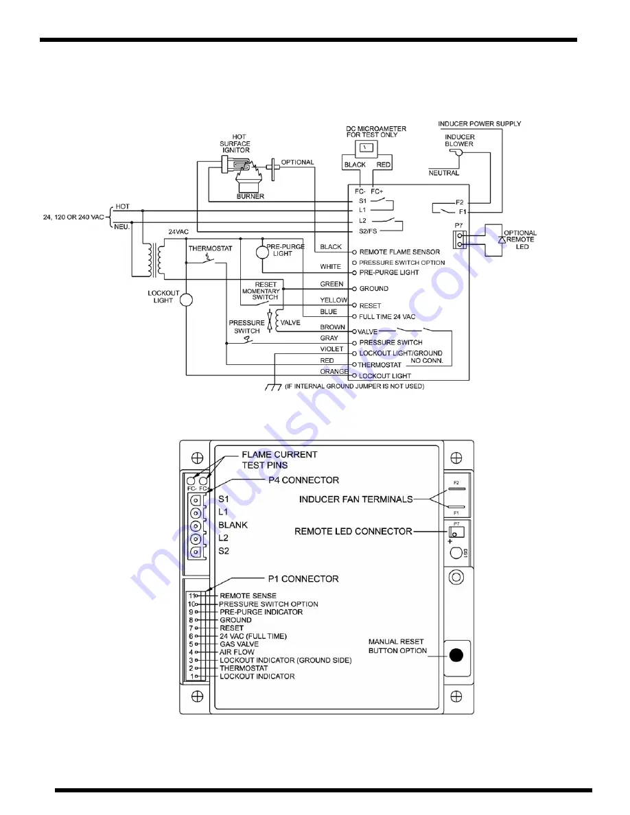
OPTIONAL DESIGN - MANUAL RESET
WIRING
Figure 4B
PIN LAYOUT
Figure 5B
Page 1: ...h LED output provide assistance with troubleshooting to ensure safe and efficient burner operation Agency Certifications Design certified by CSA International to CAN C22 2 199 M89 and ANSI Z21 20 for Automatic Ignition Systems including UL1998 Software Review Special models approved to EN298 2003 available upon request SERIES 35 67 24 VAC Microprocessor Based Proven HSI Control with Combustion Blo...
Page 2: ...current through the ignition element When the current reaches a pre determined level the LED will flash once Dwell Time From the point when the current has been proven there will be a delay called dwell time Dwell time assures that the ignition element has sufficient time to reach ignition temperature 4 IGNITION When dwell time is completed the gas valve will open The ignition element will turn of...
Page 3: ...fications could result in failure of the Fenwal product and other equipment with injury or death to people and damage to property Service to this product should only be preformed by a qualified technician 5 Series 35 67 24 VAC Hot Surface Ignition Control Page 3 www fenwalcontrols com 1 800 FENWAL 1 PIN LOCATION 1 2 3 4 5 6 7 8 9 10 11 WIRE COLOR ORANGE RED VIOLET GRAY BROWN BLUE YELLOW GREEN WHIT...
Page 4: ...lect the proper harness based on the 35 67 control s termination connection Once the terminal configuration is determined complete the part number by replacing the last two digits XX with the length in inches l dimension Standard wire lengths are 12 18 24 30 36 and 48 inches Example 05 129845 018 18 inches For other lengths please contact Fenwal Part Number 22 100001 110 REMOTE FLAME SENSE ROD ...
Page 5: ...Series 35 67 24 VAC Hot Surface Ignition Control Page 5 www fenwalcontrols com 1 800 FENWAL 1 WIRING Figure 4A STANDARD DESIGN AUTOMATIC RESET PIN LAYOUT Figure 5A ...
Page 6: ...www fenwalcontrols com 1 800 FENWAL 1 Page 6 Series 35 67 24 VAC Hot Surface Ignition Control OPTIONAL DESIGN MANUAL RESET WIRING Figure 4B PIN LAYOUT Figure 5B ...
Page 7: ...Series 35 67 24 VAC Hot Surface Ignition Control Page 7 www fenwalcontrols com 1 800 FENWAL 1 DIMENSIONS Figure 6 Figure 7 ...
Page 8: ...ge 30 Interpurge 30 Postpurge Full Time Power 7 0 Prepurge 15 Interpurge 15 Postpurge Full Time Power 8 0 Prepurge 30 Interpurge 30 Postpurge Full Time Power Tries For Ignition 0 Single Try Local Sense Recycle On Flame Loss 1 Single Try Remote Sense Recycle On Flame Loss 2 Single Try Local Sense Lockout On Flame Loss 3 Single Try Remote Sense Lockout On Flame Loss 5 Three Tries Local Sense Recycle...