background image

77

ESPAÑOL

1. INTRODUCCIÓN

El presente manual de instrucciones ha sido 

realizado en conformidad con los requisitos 

de la Directiva de Máquinas CE 2006/42/EG.

El manual de instrucciones representa par-

te integrante de la torre elevadora, debe ser 

consultado antes, durante y después de la 

puesta en marcha de la torre así como cada 

vez que se considere necesario, respetando su 

contenido en todas y cada una de sus partes.

Solamente de este modo se podrán alcanzar 

los objetivos fundamentales que se han esta-

blecido en la base de este manual como son 

prevenir riesgos de accidentes y optimizar lo 

máximo posible las prestaciones de la torre 

elevadora.

En el marco de dicho manual se han cuida-

do minuciosamente los aspectos correspon-

dientes a la seguridad y a la prevención de 

accidentes en el trabajo durante la utilización 

de la máquina destacando las informaciones 

que son de mayor interés para el usuario.

ATENCIÓN: ANTES DE UTILIZAR LA 

TORRE ELEVADORA, 

LEA ATENTAMENTE ESTE MANUAL

2. DATOS GENERALES
2.1. Datos técnicos:
Denominación: 

TORRE ELEVADORA

Modelo

: HERCULES 6.5

Características técnicas:

Altura máxima: 6,50m.

Altura mínima: 1,99m.

Carga máxima: 350kg.

Carga mínima: 25kg.

Material: Aluminio según AL Si 6106 / T6.

Área de la base abierta: 2,50 x 2,28m.

Área de la base cerrada: 0,52 x 0,65m.

Peso: 184kg.

Cabestrante: 1.700kg de carga máxima con 

freno automático de retención de la carga.

Cable: Acero galvanizado según EN 12385-4. 

Carga máxima cable: 2.000kg.

Resistencia a la torsión cable: 1.770N/mm². 

Diámetro cable: 6mm. 

Composición cable: 7x19+0.

Sistema de seguridad por péndulo interno 

más gatillo externo en tramos.

Anclaje de las patas por gatillos de seguridad.

Nivel de burbuja para ajustar posición verti-

cal de la torre.

Descripción del equipo:

La torre elevadora HERCULES 6.5 ha sido 

diseñada para levantar estructuras y aparatos 

de iluminación y sonido en sentido vertical a 

diferentes alturas.

Ha sido probada por personal capacitado 

habiendo superado todas las inspecciones de 

funcionamiento, carga máxima y dimensio-

nes.

Empresa

: FENIX Stage, S.L.U. 

Dirección:

 Avda. de los Trabajadores, 24

Horno de Alcedo - 46026 - Valencia (España)

2.2.- Normativa de aplicación

- Directiva de máquinas CE 2006/42/EG.

- BGV C1 (GUV 6.175).

- BGG 912 (GUV 66.15, GUV G-912).

- EN 12385-4:2008-06.

- DIN EN 10305-3:2010-05.

Summary of Contents for HERCULES 6.5

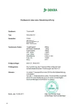
Page 1: ...rial No Instrucciones Instructions LIFTING TOWERS Fabricante Manufacturer FENIX Stage S L U FENIX Stage S L U Avda de los Trabajadores 24 Horno de Alcedo 46026 Valencia Spain Tel 34 96 125 08 55 export fenixstage com www fenixstage com www fenixstage com ...

Page 2: ...2 2 FENIX STAGE S L U Avda de los Trabajadores 24 Horno de Alcedo 46026 Valencia Spain ...

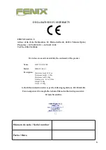
Page 3: ...lity the conformity of the product Name Model Description to which this declaration refers as per the following regulations CE 2006 42 EG Person empowered to compile the technical file and authorised represntative Mª Julia Niza del Rio LIFITNG TOWER HERCULES 6 5 Maximum height 6 50m Minimum height 1 99m Maximum load 350kg Working area 2 50 x 2 28m Weight 184kg Winch 1 700kg Número de serie Serial ...

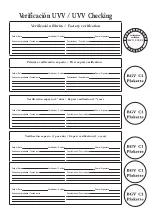
Page 4: ...usions Fecha Date Verificador Verifier Firma Signature Partes comprobadas Tested parts Conclusiones Conclusions Fecha Date Verificador Verifier Firma Signature Partes comprobadas Tested parts Conclusiones Conclusions Fecha Date Verificador Verifier Firma Signature 1 2 3 4 5 6 7 8 9 1 0 1 1 1 2 14 15 16 17 18 19 BGV C1 BGG 912 verificado en verified on Primera verificación experto First expert veri...

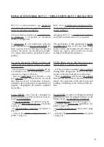
Page 5: ... punto 3 pág 8 seguir las instrucciones de uso ver punto 4 pág 9 un manteniminto periódico ver punto 5 pág 10 conocer los sistemas de prevención ver punto 7 pág 11 BGV C1 is a regulation for staging and pro duction facilities for the entertainment and events industry Adopting BGV C1 is completely voluntary except in Germany where it is required The application of this regulation is highly recommen...

Page 6: ... DE SEGURIDAD 8 4 INSTRUCCIONES DE USO 9 5 MANTENIMIENTO 10 6 RIESGOS ESPECÍFICOS 10 7 SISTEMAS DE PREVENCIÓN 11 INDEX 1 INTRODUCTION 12 2 GENERAL DATA 12 2 1 Technical data 12 2 2 Applicable regulations 12 3 GENERAL SAFETY RULES 13 4 HOW TO USE 14 5 MAINTENANCE 15 6 SPECIFIC RISKS 15 7 PREVENTION SYSTEMS 16 ...

Page 7: ... TORRE ELEVADORA Modelo HERCULES 6 5 Características técnicas Altura máxima 6 50m Altura mínima 1 99m Carga máxima 350kg Carga mínima 25kg Material Aluminio según AL Si 6106 T6 Área de la base abierta 2 50 x 2 28m Área de la base cerrada 0 52 x 0 65m Peso 184kg Cabestrante 1 700kg de carga máxima con freno automático de retención de la carga Cable Acero galvanizado según EN 12385 4 Carga máxima ca...

Page 8: ... elevadora ni apoyarlas en él para realizar ningún tipo de trabajo Tenga cuidado con todo tipo de salientes por encima de la torre elevadora como cornisas balcones letreros luminosos etc Es muy importante evitar la presencia de cables por debajo de la altura de trabajo de la torre elevadora Nunca se debe desplazar la torre elevadora si ésta se encuentra con la carga elevada No es aconsejable reali...

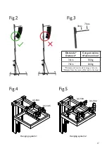
Page 9: ...s puntos de volado Ver fig 4 pág 17 En el caso de que el bumper tenga cuatro anclajes perimetrales se recomeienda utilizar los accesorios AC 582 y AC 583 que permiten levantar el equipo de sonido desde cuatro pun tos Ver fig 5 pág 17 9 Elevación Para elevar los perfiles hay que seguir un orden concreto El primer perfil que hay que subir siempre será el más alejado del cabestrante Liberar el gatill...

Page 10: ...ión cerrada S Exceptuando el carro X que se quedará fijado arriba con el gatillo de seguridad A y con los brazos de carga E orientados hacia abajo fijando así el carro X para no sufrir bloqueos del pén dulo Sacar los brazos de apoyo frontales O de sus puntos de anclaje P y colocarlos en su pletina de transporte D fijándolos con los pasadores de seguridad M y N Meter las patas H en su soporte para ...

Page 11: ...N Sobre fallo del sistema de freno Disponer de cabestrante conforme a las nor mas mencionadas en la directiva de seguri dad BGV C1 especialmente DIN EN ISO 12100 2011 03 y DIN EN ISO 12100 1 2004 04 Sobre pérdida de estabilidad El mantenimiento de la estabilidad de la to rre elevadora debe realizarse básicamente con las siguientes medidas Profesionalización adiestramiento forma ción y concienciaci...

Page 12: ... 5 Technical characteristics Maximum height 6 50m Minimum height 1 99m Maximum load 350kg Minimum load 25kg Material Aluminium AL Si 6106 T6 Open base area 2 50 x 2 28m Closed base area 0 52 x 0 65m Weight 184kg Winch 1 700kg maximum load with auto matic load retention brake Cable Galvanized steel under EN 12385 4 Maximum load cable 2 000kg Torsion resistance cable 1 770N mm Diameter cable 6mm Com...

Page 13: ...e lifting tower or lean against it for any kind of work Beware of any kind of projection above the lifting tower like cornices balconies luminous signs etc It is very important to avoid the presence of cables below the lifting tower s working height Never move the lifting tower when the load is raised It is inadvisable to make any kind of movement even small positioning adjustments Never use the l...

Page 14: ... line array s bumper has four hanging points it is recommended to use the accessories AC 582 and AC 583 which enable to fly the line array system from four hanging points See fig 5 page 17 9 Elevation To lift the profiles a specific order must be followed The first profile to be raised will always be the one located furthest from the winch Release the safety pin A in open posi tion T and turn the ...

Page 15: ...ion S With the exception of the carriage X which will remain fixed at the top with the safety pin A and the forklifts E pointing down securing the carriage X to avoid the block of the pendulum Remove the front support braces O from its anchoring support P and pla ce them to their transport support D fixing them with the safety pins M N Place the outriggers H in their transport support C and retigh...

Page 16: ...la tions metioned in the BGV C1 directive spe cially DIN EN ISO 12100 2011 03 and DIN EN ISO 12100 1 2004 04 About loss of stability Maintenance of lifting tower stability must basically be as per the following measures Professionalization training and risk awareness of lifting tower users Equip with different safety devices and ad vices from the manufacturer to reinforce sta bility as Safety pins...

Page 17: ... 1 Hanging system 2 AC 584 AC 585 AC 583 AC 582 Distancia Distance Carga máxima Maximum load 30cm 350kg 70cm 260kg Distancia del centro de la carga a la torre Distance from the center of the load to the tower 30cm 70cm ...

Page 18: ...18 ...

Page 19: ...19 ...

Page 20: ...20 ...

Page 21: ...21 ...

Page 22: ...22 ...

Page 23: ...23 NOTAS NOTES LIFTING TOWERS ...

Page 24: ...FENIX Stage S L U FENIX Stage S L U Avda de los Trabajadores 24 Horno de Alcedo 46026 Valencia Spain Tel 34 96 125 08 55 export fenixstage com www fenixstage com www fenixstage com ...

Reviews: