3.
CONNECTORS AND CONTROLS
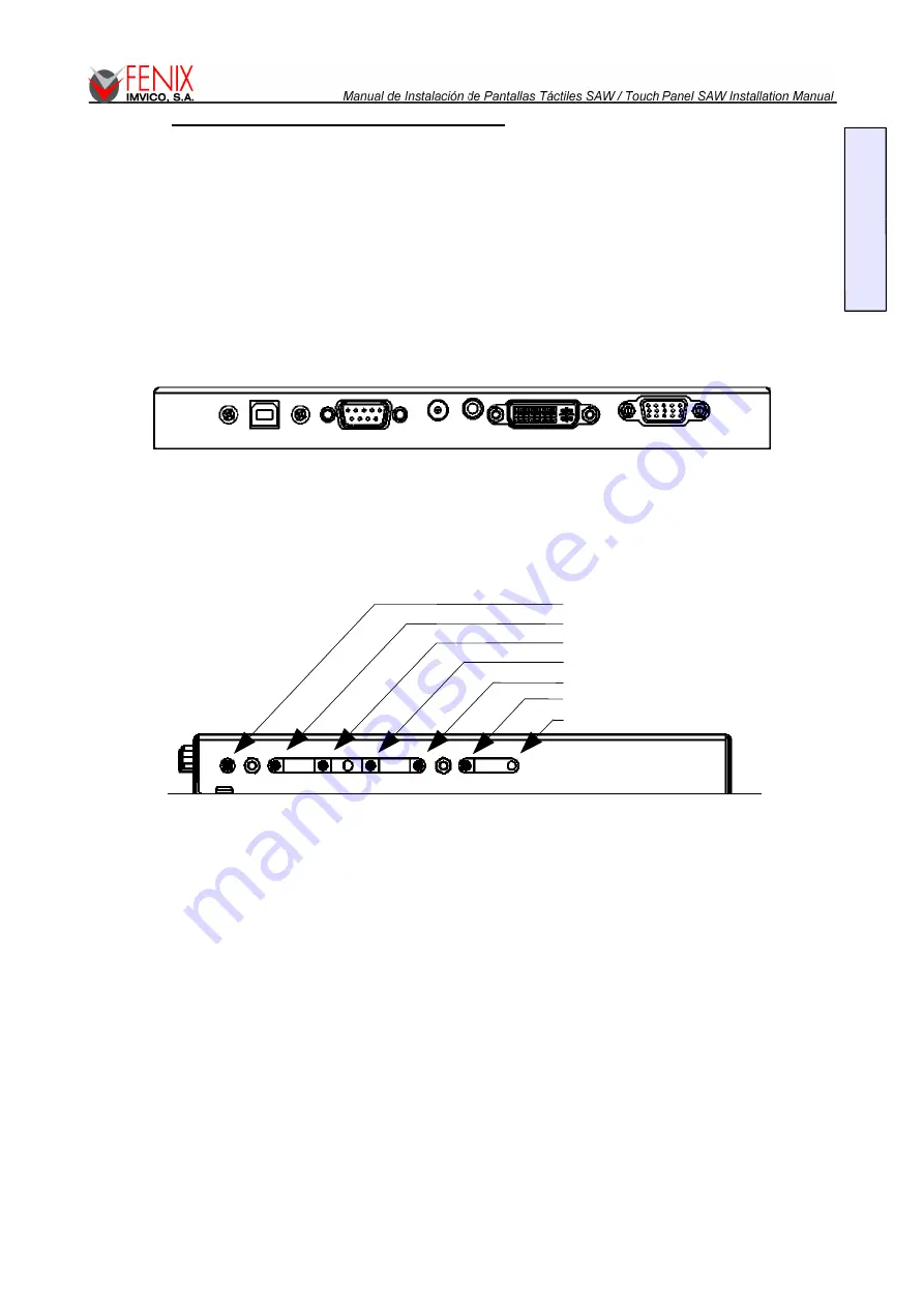
At the bottom side of the rear cover are located all the connectors. Below there is a description of the
connectors that can be seen from left to right:
–
USB co
nnector (USB1.1)
–
DB9 connector for serial connection. EIA 232E (Serial RS-232),DCE configuration. 8 Data Bits, 1
Stop Bit, No Parity, Full Duplex. 9600 bps.
–
12VDC 3.5A power supply connector.
–
DVI (Digital Video Interface) connector.
–
VGA Connector.
–
fig 3.
Connectors located at the rear cover.
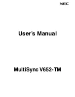
On one side of the rear cover are located all the switches and the led with the funcionality is described
below::
fig 4.
Controls on the rear cover.
•
Auto:
Clicking this switch will auto-adjusted the image inside the active display area.
•
Menú:
Enters the set-up menu.
•
Select:
Selects the current option among the possible of the menu.
•
Down:
Moves the menu cursor down.
•
Up:
Moves the menu cursor up.
•
On/Off:
This button switches On or Off the graphic screen. It does nothing on the touch
device which will be on as long as the power supply is connected.
•
Led On/Off:
Indicates by red color that the graphic screen is powered but not operative and
by green that it is powered and working.
22/35
E
N
G
L
IS
H
switch Menu
switch Down
switch On/Off
switch Auto
switch Select
switch Up
Led On/Off


