background image

TM

FENIEX.


2016 

INSTRUCTION MANUAL

WEB.


www.feniex.com

17

FAQ

Important! Do not reverse-connect the 

4200 relay, by switching the red positive 

12V(+) wire with the ground 12V(-) wire.

13. Can I change button labels on the 

App for handheld device?

Yes. If using Android app, press and hold 

button on handheld device. Enter new 

name for button when text box appears. 

On Apple app, select “settings” to edit 

labels on buttons.

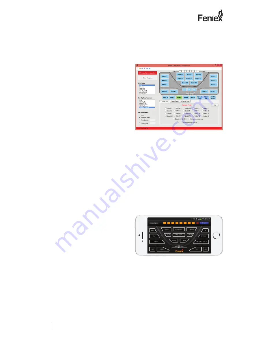
Fig 7.2

Fig 7.3

8. Can I still use my high beams with the 

WigWag function?

Yes, please use the wiring diagram (see fig. 

7.1) as a reference.

• To program, select Input C, D, or E

• Select “Highbeam Override” (see right, 

fig 7.2). 

9. How do I use my wig wag option?

Each output will support 1 high beam light 

assembly. This option can be used for low 

beams. Make sure to wire each output to 

the positive side of the high beam or low 

beam. Be sure to completely cut the wire to 

not splice into it to percent feedback.

10. How do I wire the "highbeam" 

function from the vehicle?

Run the "switch side" wire, after its cut off 

from the high beam bulb, into the 4200's 

input (C,D or E). In the programming 

software, select the input of the vehicle's 

highbeam wire and on the left column of 

the programmer under "Wig Wag Function" 

select "high beam" override.

11. My controller button is not 

illuminating?

Make sure to provide 12V+ into Input G 

(day mode).

12. The program software will not 

acknowledge my 4200 controller.

Make sure the 4200 control panel is 

plugged in via provided USB to the 

computer.

V

3.1

Summary of Contents for C-4200

Page 1: ...terial of Feniex and its licensors contained herein or in the Feniex products described in this Price List may not be copied reproduced distributed merged or modified transmitted transcribed stored in...

Page 2: ...ight 3 Feniex Product Copyright 3 Box Contents 4 System Specification 6 Wiring Diagram 7 Control Head Mounting 8 Vertical Mount 8 Surface Mount 8 Power Supply Mounting Installation 9 Configuration Rec...

Page 3: ...the previously listed products of Feniex Industries Inc Please read this manual thoroughly before installing or operating your new product in order to prevent any damage or injury Failure to follow th...

Page 4: ...ntent Diagram Unmarked RJ45 Port Labeled RJ45 Port Input Terminal Block 30A Fuse Positive Ground USB Port not used Output Terminal Blocks Important Do not use the unmarked RJ45 slot This is an unactiv...

Page 5: ...TM FENIEX 2016 INSTRUCTION MANUAL WEB www feniex com 5 RJ45 Port Slide Switch USB Port U Shaped Bracket USB Cable RJ45 Cable Legend Label Sheets Content Diagram V3 1...

Page 6: ...oltage System Specification Input Voltage 11VDC to 16VDC Temperature Range 40C to 70CV Stand By Current 100m Amps Logic Input A B Ground Logic Input C D E Positive Logic Input F Night Mode Logic Input...

Page 7: ...10 Amps WigWag 10 Amps WigWag 10 Amps 10 Amps 10 Amps 10 Amps 10 Amps 10 Amps 10 Amps 10 Amps 10 Amps 10 Amps 10 Amps 10 Amps 10 Amps 30 Amps Continuous Current 10 Amps 10 Amps 10 Amps 10 Amps Ground...

Page 8: ...s located on either side of the controller Step 3 Place the U Shaped bracket into place and screw the two factory provided screws back on each side of the controller Step 4 Connect the RJ45 cable to t...

Page 9: ...ure connectivity Step 3 Firmly secure each wire into its desired port Step 4 Firmly secure the RJ45 harness previously connected to controller into the marked RJ45 port Step 5 Apply power and ground t...

Page 10: ...ed to each outlet to assist when programming the control head with the provided software package Outputs Buttons 1 18 P1 P3 3 4 5 6 7 8 9 10 11 12 13 14 15 16 17 18 19 20 21 22 23 24 25 26 27 28 29 32...

Page 11: ...RUCTION MANUAL WEB www feniex com 11 E D C B A Inputs Controller USB 32 31 30 29 28 27 26 25 24 23 22 21 20 19 18 17 3 4 5 6 7 8 9 10 11 12 13 14 15 16 T1 T8 Used for traffic advisor lightbars Configu...

Page 12: ..._id 247 The file size is 50MB so the file may be slow to download depending on the internet connection Help For help on how to use the software please click the help button located on the top bar in t...

Page 13: ...nnected see figures 5 2 and 5 3 Step 3 Program the buttons using the software Use the help icon see figure 5 1 for instructional videos on the following categories Input Programming Traffic Controller...

Page 14: ...lation instructions below to pair the 4200 with a smart phone or tablet Power LED Indicator Pairing Switch Button hold for 3 seconds Controller Port Power Supply Port Power Supply Port RJ45 Port Step...

Page 15: ...he current Android version is 4 4 Apple App should work on the following devices iPhone 4S iPhone 5 iPhone 5C iPhone 5S iPad Air iPod Touch 5th Generation iPad 3rd 4th Generation Devices must have Blu...

Page 16: ...gray wire product directional wires to T1 T8 Use one of available outputs from 3 28 for your LED Halogen Bulb High beam Factory Harness Fig 7 1 directional needs If you would like the light stick to w...

Page 17: ...my wig wag option Each output will support 1 high beam light assembly This option can be used for low beams Make sure to wire each output to the positive side of the high beam or low beam Be sure to...

Reviews: