13
ADJUSTING DEPTH OF CUT
WARNING! Disconnect tool from power source
There are two methods for adjusting the depth of
cut on the RF67/2200 Router. The Depth
Adjustment Knob (A) is best for non plunging
operations. The Depth Stop Turret (I) and Turret
Stop Rod (D) is best for operations where there
are repeatable depth settings or two or more
depth settings may be needed.
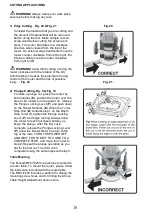
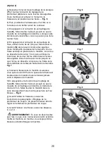
1) Depth Adjustment Knob: –Fig 9.
When Plunge Locking Lever (P) is released,
the Depth Adjustment Knob (A) may be used
to raise and lower the router motor. Turn the
knob clockwise to increase the depth of cut
and counter-clockwise to reduce the depth
of cut. Once the desired depth of cut is
reached, push up on the Plunge Locking
Lever (P) to lock the setting. Always
be sure that the Plunge Locking Lever (P)
has been released and the Turret Stop Rod
(D) cannot hit a stop on the Turret (I) before
using the Depth Adjustment Knob (A). If
router is mounted in a router table, insert the
Depth Adjustment Wrench (M) into the Above
Table Height Adjustment Access (L) to raise
and lower the router motor. Turn the wrench
counter-clockwise to increase the depth of
cut and clockwise to reduce the depth of
cut.
Note: The Depth Adjustment Wrench (M) can
be inserted into the Depth Adjustment Knob
(A) and used to adjust the depth of cut.
2) Depth Stop Turret and Turret Stop Rod:
–Fig 10. The Depth Stop Turret (I) and Turret
Stop Rod (D) allow you to preset up to three
cut depths. For maximum plunge action, the
Depth Adjustment Knob (A) must be turned
counter-clockwise until the motor is at the
top of the rods. For fine adjustment of the
cutting depth, there are three stops attached
to the Depth Stop Turret (I) on the Base of
the RF67/2200. The Depth Stop Turret turns
so that each of the three stops can be
positioned under the Turret Stop Rod (D).
The Turret Stop Rod (D) has a Course
Adjustment Knob (F) that raises or lowers
the Turret Stop Rod to make large
Fig. 9
Fig. 10


