


IDENTIFICATION
ID LR(M)5400
Installation and mounting
Installation
Page 19 of 30
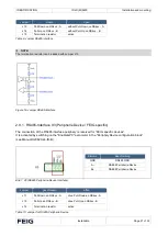
2.7
Relay REL1, REL2
The relay outputs are all a normally open contact. These outputs, which are located on terminals X2, are
galvanically isolated from the Reader electronics and must therefore be externally supplied. The external
voltage may however be provided by the card using jumper J7;J8;J9.
The two outputs are identical and can be configured individually.
Figure 18: Relay Outputs on terminal X2
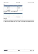
Figure 19: Internal and possible external wiring of the
relay
output’s
Jumper
Relay
Jumper
Description
REL1 (X2)
J7
Power supply VDC
REL2 (X2)
J8
Power supply VDC
Table 7: Jumper settings
Settings internal or external power supply
Power supply
Jumper: J7, J8, J9
External power supply (U
external
)
open
Internal VDC power supply U
internal
)
closed
Table 8: Internal- / External voltage supply
NOTE:
•
The relay output is configured for max. 24 VDC/ 1 A.
•
The relay output is intended for switching resistive loads only. If an inductive load is connected, the relay contacts
must be protected by means of an external protection circuit.
•
The internal 24 VDC voltage for supplying the DC voltage on the relays is not protected by the fuse F1.
•
Using internal and external voltage at the same time can destroy the reader.


