background image

IDENTIFICATION 

ID LR(M)5400 

Installation and mounting 


Installation 

Page 10 of 30 


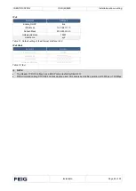
The following points must be observed to utilize the full performance of the reader module: 


The thermal resistance RThK of the heat sink must not exceed a maximum of 1.0 K/W. 

R

ThK 

≤ 1,0 K/W 


The heat transfer resistance between the carrier plate and the heat sink should be as low as 
possible. 


The use of thermal paste is recommended. 


NOTE: 


With an optimally tuned antenna and sufficient air convection along the mounting plate, the ID LRM5400 can also be 
operated up to a power of 2 W without an additional heat sink.  


Detuning the antenna always leads to additional heating of the reader. In this case, the reader regulates its output 
power back until the upper limit temperature of its output stage is undershot again. 

Summary of Contents for ID LR5400

Page 1: ...technik GmbH Co KG LESKANPARK Building 10 Waltherstr 49 51 51069 Cologne Germany Tel 49 221 8888950 hf tuev nord de Annex acc to FCC Title 47 CFR Part 15 relating to FEIG ELECTRONIC GmbH ID LRM5400 An...

Page 2: ...ID LRM5400 FCC ID PJMLRM5400 FCC Title 47 CFR Part 15 Date of issue 2023 03 09 V1 23 T V NORD Hochfrequenztechnik GmbH Co KG LESKANPARK Building 10 Waltherstr 49 51 51069 Cologne Germany Tel 49 221 8...

Page 3: ...IDENTIFICATION M21023 0e ID B Installation ID LR5400 ID LRM5400 Long Range Reader ID LR5400 Housing ID LRM5400 Modul...

Page 4: ...not be completely avoided we are always grateful for your useful tips The instructions given in this manual are based on advantageous boundary conditions FEIG ELECTRONIC GmbH does not give any guaran...

Page 5: ...an incorrect application of a device Repairs may only be executed by the manufacturer Installation operation and maintenance procedures have to be carried out by professional and qualified personnel...

Page 6: ...IDENTIFICATION ID LR M 5400 History of Documentation Installation Page 4 of 30 History of Documentation Revision Date Description 0e english October 2022 Initial Version...

Page 7: ...uts IN1 IN2 IN3 16 2 6 Digital outputs OUT1 OUT2 18 2 7 Relay REL1 REL2 19 2 8 Power supply 24 VDC GND 20 2 9 Interface 20 2 9 1 RS485 Interface X3 Host 20 2 9 1 RS485 Interface X3 Peripherie Device F...

Page 8: ...IDENTIFICATION ID LR M 5400 Content Installation Page 6 of 30 5 Technical Data 28...

Page 9: ...al antennas The connection to a computer or other device host is made via one of the three interfaces Schnittstellen RS485 USB LAN Operating frequency f 13 56 MHz NOTE For the operation it is necessar...

Page 10: ...n Page 8 of 30 2 Installation and mounting 2 1 Installation The reader module is designed for mounting on a heat sink For mounting there are five holes each with 4 5 mm marked yellow in the carrier pl...

Page 11: ...IDENTIFICATION ID LR M 5400 Installation and mounting Installation Page 9 of 30 Figure 3 Front view readermodul Figure 4 Top view readermodul with bolt holes...

Page 12: ...e between the carrier plate and the heat sink should be as low as possible The use of thermal paste is recommended NOTE With an optimally tuned antenna and sufficient air convection along the mounting...

Page 13: ...ion and mounting Installation Page 11 of 30 2 2 Control elements and connection terminals Terminals X1 X6 LED V1 V6 Jumper J1 J15 Antenna terminals ANT1 ANT4 Figure 5 Marked terminals jumper and LEDs...

Page 14: ...f the housing Figure 7 Cable glands on the underside of the housing Cable gland Size Clamping range mm Description 1 M16 4 5 10 mm 4 5mm 10mm ANT2 2 4 5mm 10mm I O 3 4 5mm 10mm I O 4 4 5mm 10mm ANT1 5...

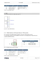
Page 15: ...stallation and mounting Installation Page 13 of 30 Cable routing Figure 8 Arrangement of the connecting cables 2 2 2 Open the cover The latch on the housing cover must be pressed outward with a screwd...

Page 16: ...optimum length of the coaxial cable is 1 35 m article no 1654 004 00 00 designation ID ANT C B See also installation instructions Power Splitter ID ANT PS B and ID ANT MUX The optimum operating qualit...

Page 17: ...C Supply voltage 24 V X6 Pin 2 GND Ground Table 3 Pin outs for supply voltage on X6 Figure 11 Position of the connector X6 for the power supply NOTE Make sure that the supply voltage is connected corr...

Page 18: ...e reader The 3 inputs are individually configurable Figure 12 X2 Digital Inputs IN1 IN2 IN3 External power supply Figure 13 External power supply for the digital inputs Internal power supply Figure 14...

Page 19: ...IN3 Setting internal or external power supply Power supply Jumper J2 J4 J6 External power supply Uexternal open Internal VDC power supply Uinternal closed Table 5 Select power supply external series...

Page 20: ...any internal ancillary circuitry on terminal X2 The output must therefore be powered by an external power supply Figure 15 Digital output on X2 Ext power supply Figure 16 External power supply Int pow...

Page 21: ...relay output s Jumper Relay Jumper Description REL1 X2 J7 Power supply VDC REL2 X2 J8 Power supply VDC Table 7 Jumper settings Settings internal or external power supply Power supply Jumper J7 J8 J9...

Page 22: ...supply NOTE For the dimensioning of the power supply the power consumption for the external output circuitry must be additional considered to the typical reader power consumption The internal 24VDC vo...

Page 23: ...ace X3 Peripherie Device FEIG specific The connection of the RS485 interface periphery is reserved for FEIG specific devices It is activated by switching on the EnableGPC parameter in the PeripheryDev...

Page 24: ...gned by the host computer The software is used to assign addresses 0 through 254 to the Reader The termination of the RS485 Bus can be configured via software NOTE Since all Readers are factory set wi...

Page 25: ...SB Host interface X5 2 9 4 Ethernet Interface on X1 10 100 Base T Connection on X1 Integrated 10 100 Base T Network port for an RJ 45 Automatic Crossover Detection Figure 24 LAN interface for Host com...

Page 26: ...ostname xyz Table 11 Default setting of the Ethernet interface IPv4 IPv6 tbd Netzwerk Adresse Enable_DHCP false IPAddress 0 0 0 0 0 0 0 0 Subnet Mask 0 0 0 0 0 0 0 0 GatewayAddress 0 0 0 0 0 0 0 0 Tab...

Page 27: ...h V1 if a data error occurred when reading the parameters after a reset LED V3 PER COM Diagnose 2 Periphery communication Yellow LED ON OFF ON A protocol is sent to the gate via RS485 OFF Receiving a...

Page 28: ...ext of the EU declaration of conformity is available at the following internet address https www feig de en service eu declarations of conformity UKCA Declaration of Conformity Hereby FEIG ELECTRONIC...

Page 29: ...is likely to cause harmful interference in which case the user will be required to correct the interference at his own expense Le pr sent appareil est conforme aux CNR d Industrie Canada applicables a...

Page 30: ...t wiring Antenna connection 4 x SMA socket 50 Modulation 10 30 Software configurable DC Supply at Antenna Connector 8 VDC max 150 mA Diagnostic Options internal VSWR Meter interne temperature monitori...

Page 31: ...tions Temperature range In operation Stored 20 C 55 C 25 C 85 C Humidity 5 80 non condensing Vibration EN 60068 2 6 10 Hz to 150 Hz 0 075 mm 1 g Shock EN60068 2 27 Acceleration 30 g Applicable standar...

Page 32: ...ent Version M21023 0e ID B Date 18 10 2022 Copyright All cited brand names product names or trademarks belong to their respective holders FEIG ELECTRONIC GmbH Industriestra e 1a 35781 Weilburg Germany...

Reviews: