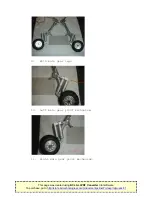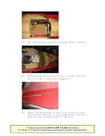
screws at the retract units and check that the lower part
twists at the shock strut (as per the real aircraft). If
not it is probably dirty with paint inside and you will
need to take it apart, clean it out and give it some
light grease for lubrication. See 2.1.Carefully inspect
and clean all parts.
2.
Landing gear and doors. Before the space get invaded
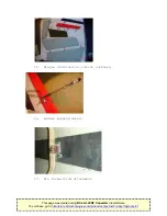
check each and every door actuator individually for leaks
and free and correct operation. Fit colour coded air line
to the up and down sides and route towards the position
where you plan to install the valves with some tubing to
spare.
2.1
Main gear. Check the fit of the main gears for its length
and position with the wheels twisted upwards and that the
door actuators do not interfere with its operation.
Remove the unused round bits of the door hinges with a
rotary tool (Dremel) to avoid it jamming with wheels or
air lines. Next check the operation of the twisting
rod.Check the secondary gear actuators and its fittings
if you plan to use them. (Do the fuel tank and mark all
air lines and servo extensions
before
joining the nose
section to the fuselage!!) After the nose is connected to
the fuselage you can continue with the following:Check
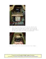
the air bottles for leaks and fit them in the lower
fuselage behind the main landing gear former. The bottle
for the brakes goes in the nose. The Jet Tronics valves
for doors and brakes are fitted on the plywood nose
plate. Connect all the air lines. The filling fittings
are on top of the plywood shelf just behind the air
intake. Set up the door sequencer according to the
manufacturer’s instructions so that the doors operate
correctly in sequence with the gear. The 2 small nose
gear doors and the most rearward main gear doors stay
open when the gear is down. Once satisfied with the
alignment “permanently fix” the gear strut adding blue
Loctite and then tighten the securing bolt as tight as
possible.
2.2
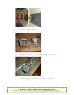
Nose gear. I filed flat spots at the high stress areas to
avoid slipping and took the opportunity to install a
direct steering system using a small metal gear servo.
Apply grease on the axles for the wheels as they do not
have bearings to prevent the wheels from seizing. When
installing the nose gear make sure nothing jams when the
gear extends or retracts. Connect all the air lines and
route the lines to the rear where you plan to install the
fill valves and air tanks. Mark every line for
identification before the nose section is joined with the
main fuselage section. I also fitted airline restrictors
in the nose gear air lines as the air demand of the nose
gear is much less that what is required for the main gear
retracts.
This page was created using BCL ALLPDF Converter trial software.
http://store.bcltechnologies.com/productcart/pc/instPrd.asp?idproduct=1


