FEG C 24 H User Manual Download Page 17

16 


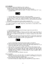
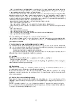
By the effect of adjustment the display changes to the adjusted value. After 2 seconds the display 
changes back and continuously shows the actual temperature of delivery heating water. 


Raise the temperature of water only when the low value does not ensure the required temperature of 
the room. 

The room thermostat ensures the adjusted temperature only in its location. 
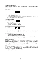
 

3.4. Shut-down 

-By turning the push-button clockwise (see Fig. 8.) the pilot flame and the burner shuts down 
immediately. 
-Following this the appliance can be disconnected from mains by pulling its plug out of the electrical 
socket. 
In 60 seconds after shutdown restart of the boiler is PROHIBITED! 
When heating is suspended during winter it is advisable in order to avoid freezing of the system to set 
a low temperature on the room thermostat and to operate the boiler like that (the temperature of the 
room can be set to 5 ºC by turning the knob counter-clockwise until it butts on). 
When DWT sensor feels temperature under 5ºC the electronics switch the boiler on heating even if 
there is not request for heating (from the part of the room thermostat). This frost protective heating 
operates until 25 ºC DWT. Reaching this value the boiler stops after 1 minute of post-circulation. 

Notes: frost protection starts to operate only when the gas supply of boiler is ensured, the pilot 
flame is burning and the mains are provided as well. 

In case of a longer interruption during danger of frost the water must be discharged from the whole 
system. 


3.5. Instructions for maintenance 

Life of the appliance can be extended by regular service and maintenance.  
The cover should be wiped occasionally with a wet, then a dry cloth to keep it free from dust. The 
parts of deflector should be cleaned as well. Using scrubbing materials or any other material, which 
can scratch the surface is PROHIBITED! 
When necessary the refill of the heating system can be made by the operator. In case of an opened-
loop until the overflow of the expansion tank and in case of a closed-loop cold heating system until 
overpressure of 1 bar that can be checked on an installed pressure-meter.  
To prevent scaling avoid change (drain down) of heating water. 
Water must not leak at the tube connections. The possible drops must be terminated by tightening or 
by change of seals. Only skilled experts may repair the gas and electric parts! 

adjustment

Display of

display

Continuous


Pilot flame

Temperature controller knob

Display

Fig. 8.

Button


Summary of Contents for C 24 H

Page 1: ...USER S MANUAL Wall mounted boiler for central heating C 24 H F t stechnikai K sz l kgy rt Ltd Hungary 6900 Mak Aradi street 136...

Page 2: ...4 FLUE GAS PIPING 7 2 5 FILLING AND PUTTING INTO OPERATION 8 2 6 ELECTRIC DESCRIPTION 8 2 7 CONNECTING OF ROOM THERMOSTAT 9 2 8 INSTALLATION 10 2 9 FROST PROTECTION 11 2 10 FIRST INSTALLATION 12 2 11...

Page 3: ...electric appliance do not move any electric wall plug do not employ an open fire In case of further gas leakage turn off the main gas valve under the gas meter The gas leakage must be reported to the...

Page 4: ...Pilot flame holder Flue gas backflow sensor Limiter thermostat Pump Electric control box Purging screw Thermocouple Gas inlet pipe 19 20 Thermistor Display A G B Delivery water Gas connection Returni...

Page 5: ...s inlet 3 Thermocouple 4 Burner 5 Heat exchanger 6 Delivery temperature sensor NTC 7 8 Flue gas backflow sensor Limiter thermostat 9 Deflector 10 Purging screw 11 11 Pilot flame pipe 12 12 Magnetic va...

Page 6: ...temperature controller 5 30 C Weight kg 22 At 15 C and 1013 mbar Table 1 2 General instructions for installation 2 1 Placement of the appliance Make sure that the wall is suitable for mounting the app...

Page 7: ...nt Gas connections The cross section of the connecting pipe must be at least the same or bigger than of the gas pipe in the boiler A closing fitting must be mounted before the appliance The furnace ca...

Page 8: ...if the boiler is placed into a cabinet then it is to be built from floor to ceiling its walls and door must be made of non burnable material If possible its door should be gridded 2 4 Flue gas piping...

Page 9: ...hed wall socket placed beside the appliance or in case of a bathroom in zone 3 and connect it to the electric network of the house Max current drain of the boiler is not bigger than 1Amper Attention T...

Page 10: ...rent input e g Floor heating module electronic temperature controller etc mains input can be connected from points 5 and 6 which inputs stop when the mains plug of boiler is disconnected Table 1 Sign...

Page 11: ...a request for heating on the part of room thermostat Turn potentiometer located on electronic panel and marked P1 by a screwdriver while checkig the display As a result of adjustment display changes f...

Page 12: ...in burner Cause of failure can be Minimum required quantity of water is not provided Temporary lack of water in the leaking heating system Notes Above 91 C the electronics consider thermistor dead sho...

Page 13: ...ce is to be modified for operation by the supplied gas SEE CHAPTER ADJUSTMENT FOR ANOTHER TYPE OF GAS gas valve must be opened leakages are to be terminated Mains 230V IN 1 2 3 4 7 8 9 10 11 12 13 141...

Page 14: ...n order to adjust the combined gas valve correctly follow the next steps Connect a pressure gauge to stub C after loosening of closing screw Pressure of connecting gas can be measured on stub E in cas...

Page 15: ...r 10 and the label on back panel 11 Adjustment from LPG to natural gas After loosening the screw M 4x8 remove the flame trap 3 altogether with the pilot flame pipe 4 After loosening of other fixing sc...

Page 16: ...er is PROHIBITED Maintenance is not an action of guarantee 3 Instructions for use and maintenance for users First installation of the appliance may only be made by an expert of the service network of...

Page 17: ...rotective heating operates until 25 C DWT Reaching this value the boiler stops after 1 minute of post circulation Notes frost protection starts to operate only when the gas supply of boiler is ensured...

Page 18: ...pliance every five years ATTENTION The boiler has got a flue gas backflow sensor When it starts operation the boiler stops automatically Restart can only be made by manual ignition of pilot flame Disa...

Reviews: