


37
Installation, Maintenance, and Service Manual
Federal Signal
www.fedsig.com
Maintaining and Servicing the Valor
Reinstalling the Lens
To reinstall the lens:
1.
Reinstall the gasket and lens. To prevent cross-threading the barrel nuts, back
them counterclockwise until you hear the click of the threads engaging.
2.
Tighten the barrel nuts to 16-24 in-lb in the sequence shown in Figure 13 on
page 36.
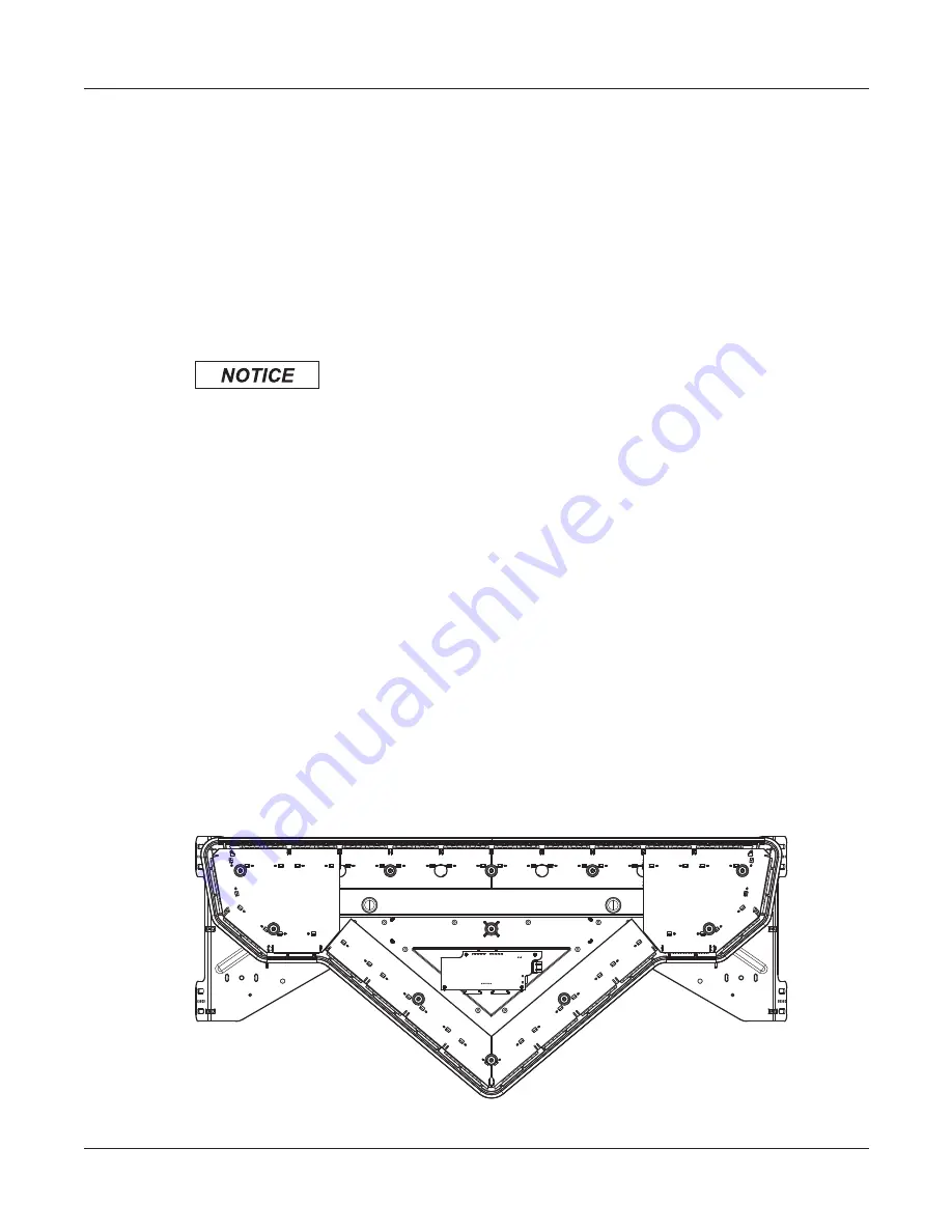
Replacing a PCB
The Valor light bar has two front, two rear, and two end ROC PCBs as well as a
controller PCB (Figure 14). They are configured at the factory per the customer order.
STATIC-SENSITIVE DEVICE: The light bar circuitry can be damaged by
electrostatic discharge (ESD). Follow anti-static procedures while installing
the light bar.
Tool required:
T27 Torx driver
Removing a PCB
To remove a PCB:
1.
Disconnect all power to the light bar at the battery or at the light bar. See
“Disconnecting/Connecting Power and CAT5 at the Light Bar” on page 38.
2.
Use a T27 Torx driver to remove the 1/4
-
20 Torx-head barrel nuts securing the lens
(Figure 13 on page 36). Carefully remove the lens and gasket as a unit. Avoid
damaging the lip seal.
3.
Verify that an O-ring is under the head of each barrel nut and not stuck to the
lens. Use a wooden or plastic pick to carefully remove the O-rings from the lens to
prevent damaging them.
Figure 14 Location of controller
FR
ON
T P
AS
SE
NGE
R-SIDE
PC
B
290A6564
FR
ON
T D
RI
VE
R-
SI
DE
PC
B
END PCB
END PCB
REAR PCB
CONTROLLER
REAR PCB


