Price $4.00
HARDWARE INSTALLATION AND MAINTENANCE INSTRUCTIONS
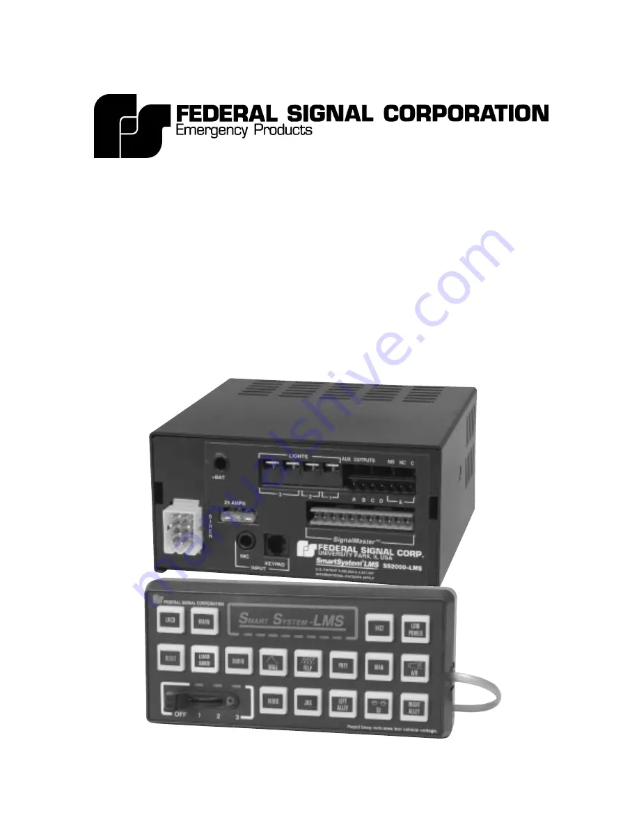
Model SS2000-LMS
SmartSystem™ Load Management System
LOAD MANAGER WITH ELECTRONIC SIREN/LIGHT
CONTROL SYSTEM AND
SignalMaster™ DIRECTIONAL LIGHT
(with Slide Switch Control Head)
Page 1: ...E INSTALLATION AND MAINTENANCE INSTRUCTIONS Model SS2000 LMS SmartSystem Load Management System LOAD MANAGER WITH ELECTRONIC SIREN LIGHT CONTROL SYSTEM AND SignalMaster DIRECTIONAL LIGHT with Slide Sw...
Page 2: ...h examination reveals a defect in material and or workmanship This warranty does not cover travel expenses the cost of specialized equipment for gaining access to the product or labor charges for remo...
Page 3: ...r WILL NOT function properly if this step is not followed 3 Is the green wire from the twelve pin connector Pin 5 connected to chassis ground AUXILIARY RELAY SIREN POWER 4 Is an 8 10 AWG wire connecte...
Page 4: ...ated into the system This system provides the automatic simulta neous light and siren activation required by some laws Momentary push on push off or timed relay operation can be selected A security sh...
Page 5: ...rval 30 seconds Adjustable Voltage Threshold Range 11 15VDC C SIREN SPECIFICATIONS Operating Current 9 amperes nominal no lamps on 13 6V battery 11 ohm load high power Frequency Range 725 to 1600Hz No...
Page 6: ...llation have compatible wattage ratings In order for the electronic siren to function properly the ground connection must be made to the NEGATIVE battery terminal Sound output will be severely reduced...
Page 7: ...snow standing water etc Also it must be installed in an adequately ventilated area Never install near heater ducts Do not mount the SS2000 LMS Amplifier Unit under the vehicle s hood Some possible Amp...
Page 8: ...ad that allows the vehicle controls and microphone to be operated safely at all times See figure 3 3 The supplied hinged mounting bracket enables the control head to be mounted in a variety of positio...
Page 9: ...s follows 1 Speaker The unit is designed to operate with one 11 ohm impedance speaker or two 11 ohm impedance low power 58W or high power 100W speakers connected in parallel and in phase On Federal sp...
Page 10: ...is the installer s responsibility to determine an appropriate location in the vehicle cir cuitry to connect the PARK NEUTRAL SAFETY wire This location should be determined prior to installation This...
Page 11: ...cle chassis as close as practical to the Amplifier Unit Scrape paint away from the selected bolt hole to assure a good electrical connection to the chassis b Power for the Amplifier Unit can be obtain...
Page 12: ...IGHTS 1 2 and 3 can be reprogrammed to activate in any of the three modes select the terminals used for the various loads in accordance with the current ratings of the terminals Primary rotating light...
Page 13: ...XILIARY RELAYS FROM INTERFACE RELAY PI 4 BLK BATTERY NOTE Although output 3 is rated at 40 amperes the circuit is protected by two 20 ampere fuses which are connected in parallel TB1 3 output 3 has tw...
Page 14: ...modular connector are exactly the same as the original cable connections To complete this portion of the installation proceed as follows 1 Route the 20 foot cable between the SS2000 LMS control head a...
Page 15: ...f this manual to all operating personnel C Ensure that there are no loose wire strands or other bare wire which may cause a short circuit Also all wires must be protected from any sharp edges which co...
Page 16: ...e signaling devices does not give you the right to force your way through traffic Your emergency lights siren and actions are REQUESTING the right of way Although your warning system is operating prop...
Page 17: ...st have a good understanding of automotive electrical procedures and systems along with proficiency in the installation and service of safety warning equipment Always refer to the vehicle s service ma...
Page 18: ...s described in paragraph 6 2 6 4 AMPLIFIER SIGNALMASTER RELAY UNIT A General Any competent TV repairman or electronic technician should have little difficulty in tracing a malfunction should any occur...
Page 19: ...iniature fuse F1 on the amplifier board provides short circuit protection for the control head and cable F1 is located between K3 and IC10 near the modular connector on the ampli fier board Failure of...
Page 20: ...use 7 5 Amp Automotive Blade 148A142 04 Reference Description Part Number Designation SS2000 LMS Components T2 Transformer Output 120249 QA QB Transistor Output 125468 Legend Sticker Card 8572294 02 R...