Installation and Maintenance Manual
Model 300VSC-1 and Model 300VSC-1044SB SelecTone Command Units
13
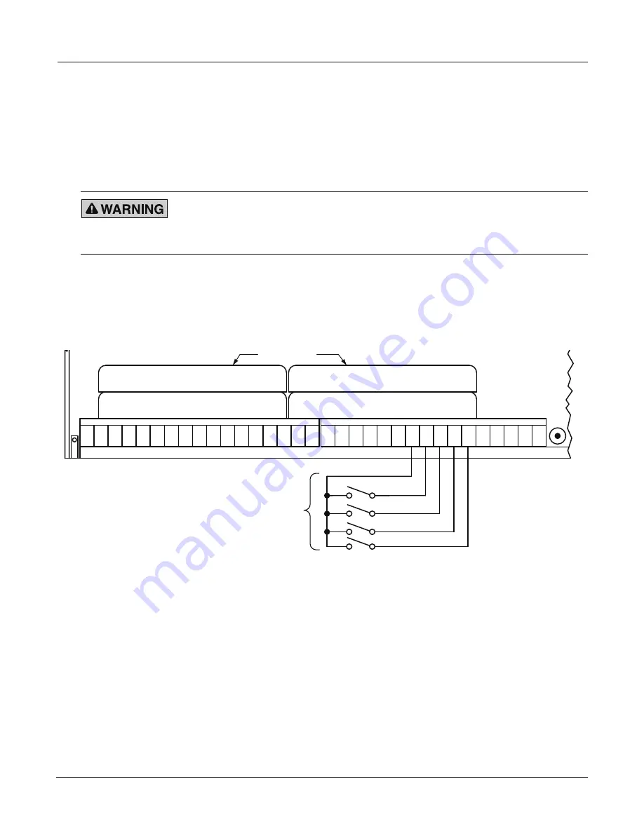
Connecting to Remote Switches for Tone Activation
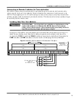
The 300VSC tones can be activated remotely by any normally open, low-current switch contacts with a
current capacity of at least 50 mA inductive. Figure 4 illustrates the connection of switch contacts to the
300VSC. The designations S1, S2, S3 and S4 represent remote switch contacts such as those found in flow
switches, program clocks, heat detectors, and smoke detectors. The remotely activated tone sounds as long as
the activating contacts remain closed.
Installing SelecTone Tone Modules
SHOCK HAZARD
—
Do not perform any installation or maintenance on this
system when power is on. Because the 300VSC does not have a power
switch, ensure that the power is disconnected before proceeding. Failure to
heed this warning may cause serious injury or death.
See Figure 4. The 300VSC can accommodate up to four SelecTone tone modules of your choice. To
install the tone modules, insert them into the desired receptacles on the printed circuit board. The
receptacles for
TONE 1
module and
TONE 2
module are located on the motherboard. Receptacles for
TONE 3
module and
TONE 4
modules are located on the card that plugs into the motherboard.
Figure 4 Remote switch contacts for tone modules 1 through 4
1 2 3 4 5 6 7 8 9 10 11 12 13 14 15 16 17
1 2
GND
TONE 1
TONE 2
TONE 3
TONE 4
3 4 5 6 7 8 9 10 11 12 13 14 15 16
TB1
TB2
300VSC-1
TONE 2
REAR VIEW
(WITHOUT COVER)
TONE 4
TONE 1
TONE 3
TONE MODULES
290A7330
OPTIONAL REMOTE SWITCH
CONTACTS
(CUSTOMER SUPPLIED)
S1
S2
S3
S4
Summary of Contents for SelecTone 300VSC-1
Page 55: ...blank page...


