background image

5

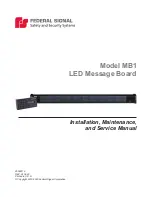
Installation, Maintenance, and Service Manual 

Federal Signal

 www.fedsig.com

Safety Message to Installers and Service Personnel of Warning Lights

During Installation and Service

•  DO NOT get metal shavings inside the product. Metal shavings in the product can 

cause the system to fail. If drilling must be done near the unit, place an ESD-approved 

cover over the unit. Inspect the unit after mounting to ensure that there are no 

shavings in or near the unit.

•  DO NOT connect this system to the vehicle battery until ALL other electrical 

connections are made, mounting of all components is complete, and you have verified 

that no shorts exist. If the wiring is shorted to the vehicle body or frame, high current 

conductors can cause hazardous sparks, resulting in electrical fires or flying molten 

metal.

•  DO NOT install equipment or route wiring (or the plug in cord) in the deployment path 

of an airbag.

•  Before mounting any components, check the manual to ensure that the component 

you are installing is suitable for use in that area of the vehicle. Many components 

are not suitable for use in the engine compartment or other extreme environmental 

exposure areas.

•  When drilling into a vehicle structure, ensure that both sides of the surface are clear 

of anything that could be damaged. Remove all burrs from drilled holes. To prevent 

electrical shorts, grommet all drilled holes through which wiring passes. Ensure that 

the mounting screws do not cause electrical or mechanical damage to the vehicle.

•  Refer to the manual packed with the lighting system for proper electrical connections, 

additional precautions, and information. 

•  Locate the light system controls so the VEHICLE and CONTROLS can be operated 

safely under all driving conditions.

After Installation or Service

•  After installation, test the light system to ensure that it is operating properly.
•  Test all vehicle functions, including horn operation, vehicle safety functions, and 

vehicle light systems, to ensure proper operation. Ensure that the installation has not 

affected the vehicle operation or changed any vehicle safety function or circuit.

•  If a vehicle seat is temporarily removed, verify with the vehicle manufacturer if the 

seat needs to be recalibrated for proper airbag deployment.

•  Scratched or dull reflectors, mirrors, or lenses will reduce the effectiveness of the 

lighting system. Avoid heavy pressure and use of caustic or petroleum based products 

when cleaning the lighting system. Replace any optical components that may have 

been scratched or crazed during system installation.

•  Do not attempt to activate or deactivate the light system control while driving in a 

hazardous situation.

•  Frequently inspect the light system to ensure that it is operating properly and is 

securely attached to the vehicle.

•  After installation and testing are complete, provide a copy of these instructions to 

instructional staff and all operating personnel.

•  File these instructions in a safe place and refer to them when maintaining and/or 

reinstalling the product.

Failure to follow all safety precautions and instructions may result in property damage, 

serious injury, or death.

Summary of Contents for MB1

Page 1: ...25500112 REV A1 0920 Printed in U S A Copyright 2015 2020 Federal Signal Corporation Model MB1 LED Message Board Installation Maintenance and Service Manual...
Page 2: ...imited warranty is in lieu of all other warranties express or implied contractual or statutory including but not limited to the warranty of merchantability warranty of fitness for a particular purpose...

Page 3: ...rols 13 Testing the Message Board System 13 Setting Configuration Options 14 Entering the Standard Menu 15 Entering the Security Menu 15 Exiting the Standard or Security Menu 15 Fleet Password and Sec...

Page 4: ...f the lighting system and may damage the components Verify or test your combination to ensure that the system works together and meets federal state and local standards or guidelines Electrical Hazard...

Page 5: ...echanical damage to the vehicle Refer to the manual packed with the lighting system for proper electrical connections additional precautions and information Locate the light system controls so the VEH...

Page 6: ...onvergence Network products For programming and operating instructions refer to Federal Signal doc no 25500056 The Message Board housing is coextruded polycarbonate with polycarbonate end caps and ela...

Page 7: ...ge 1 4 20 SS 70100531 12 2 Bolt Carriage 3 8 16 SS 7004A024 16 4 Nut Keps 1 4 20 SS 7058050 2 Nut 3 8 16 Hi Corr Resistant 7059124 4 Washer Flat 1 4 inch SS 7072A024 2 Washer Flat 3 8 inch SS 7072A035...

Page 8: ...e drilling All drilled holes should be deburred and all sharp edges should be smoothed All wire routings going through drilled holes should be protected by a grommet or convolute split loom tubing 6 D...

Page 9: ...all auxiliary devices on the light bar or the warning system may fail LOCATING OPERATOR CONTROLS The controls for the light system must be located so that the VEHICLE and CONTROLS can be operated safe...

Page 10: ...wires from the control head must be wired directly to battery power and not to a switched power source Failure to do so may reduce the lifetime of its internal battery required to keep accurate time T...

Page 11: ...n any additional Convergence Network control heads Figure 3 Convergence Network connections with siren LED MESSAGE BOARD 25 ft CAT5 290A7199B SMARTSIREN CONTROLLER LED MESSAGE BOARD CONTROL HEAD SMART...

Page 12: ...t that you fully understand how to safely operate this warning system before use Operate your vehicle and its light sound system in accordance with your department s Standard Operating Procedures If a...

Page 13: ...esight when viewed at close range Do not stare directly into the lights at close range or permanent damage to your eyesight may occur To test the Message Board system 1 Follow all the instructions in...

Page 14: ...ller during installation of the Message Creation software For more information see Fleet Password and Security on page 15 To navigate menus use the up down arrows or simply press the number associated...

Page 15: ...t Password created by the installer during installation of the Message Creation software You have three attempts to enter the Fleet Password correctly The fourth attempt locks the menu Battery power m...

Page 16: ...avigate to the Security Menu see page 14 and use the Reset Fleet Password menu option If you do not know the Fleet Password To unlock the control head 1 Disconnect and apply 12 V BAT on the yellow blu...

Page 17: ...shoe shaped wire in it to see if it has burned through and broken the circuit Figure 4 Fuse location on PCB DRIVER SIDE END CAPS PHILLIPS PLASTITE SCREW 4 ALUMINUM CARRIER 15 A BLADE FUSE ON PCB 290A7...

Page 18: ...ignal factory provides technical assistance with any problems that cannot be handled locally Any units returned to Federal Signal for service inspection or repair must be accompanied by a Return Mater...

Page 19: ...ual Federal Signal www fedsig com Ordering Replacement Parts Ordering Replacement Parts To order replacement parts please contact your local dealer distributor or Customer Support Federal Signal Corpo...

Page 20: ...l Signal Drive University Park Illinois 60484 3167 www fedsig com Customer Support Police Fire EMS 800 264 3578 1 708 534 3400 Work Truck 800 824 0254 1 708 534 3400 Technical Support 800 433 9132 1 7...

Reviews: