


4
4
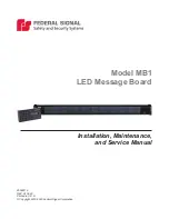
Model MB1 LED Message Board
Federal Signal
www.fedsig.com
Safety Message to Installers and Service Personnel of Warning Lights
Safety Message to Installers and Service Personnel of Warning Lights
People’s lives depend on your proper installation and servicing of Federal Signal
products. It is important to read and follow all instructions shipped with this product.
Listed below are some other important safety instructions and precautions you should
follow:
Before Installation or Service
Qualifications
• To properly install or service this equipment, you must have a good understanding of
automotive mechanical and electrical procedures and systems along with proficiency
in the installation and service of safety warning equipment. Always refer to the
vehicle’s service manuals when performing equipment installations on a vehicle.
Light Hazards
• To be an effective warning device, this product produces bright light that can be
hazardous to your eyesight when viewed at a close range. Do not stare directly into
this lighting product at a close range, or permanent damage to your eyesight may
occur.
• Do not install the light system in an area that would block, impair, or blind the driver’s
vision. Ensure that the light system is mounted in a position that is outside of the
driver’s field of vision, so the driver can safely operate the vehicle.
• Federal Signal power supplies and light heads are designed to work together as
a system. Combining light heads and a power supply from different manufacturers
may reduce the warning effectiveness of the lighting system and may damage the
components. Verify or test your combination to ensure that the system works together
and meets federal, state, and local standards or guidelines.
Electrical Hazards
• A light system is a high current system. In order for the system to function properly,
a separate negative (–) connection and positive (+) connection must be made. All
negative connections should be connected to the negative battery terminal, and a
suitable fuse should be installed on the positive battery terminal connection as close
to the battery as possible. Ensure that all wires and fuses are rated correctly to handle
the device and system amperage requirements.
• Never attempt to install aftermarket equipment that connects to the vehicle wiring
without reviewing a vehicle wiring diagram available from the vehicle manufacturer.
Ensure that your installation will not affect vehicle operation or mandated safety
functions or circuits. Always check the vehicle for proper operation after installation.
• The lighting system components, especially light bulbs, strobe tubes, LEDs, and the
outer housing, get hot during operation. Disconnect power to the system and allow
the system to cool down before handling any components of the system.
• Do not mount a radio antenna within 18 inches (45.7 cm) of the lighting system. Placing
the antenna too close to the lighting system could cause the lighting system to
malfunction or be damaged by strong radio fields. Mounting the antenna too close to
the lighting system may also cause the radio noise emitted from the lighting system to
interfere with the reception of the radio transmitter and reduce radio reception.
• Do not attempt to wash any unsealed electrical device while it is connected to its
power source.