background image

alerting signals. Either a 25 or 70 VRMS AC signal source can be used. In addition, this
loudspeaker can reproduce full range voice communication. An in-line capacitor (supplied)
provides the isolation necessary for supervisory use.

Speaker style: a high-impact plastic re-entrant housing for various applications.

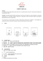
The speaker is supplied with wiring terminals and strain relief for speaker in/out

wiring (see figure 1). An optional auxiliary terminal is supplied on the speaker PC board.

B.

POWER ADJUSTMENT.

See figures 1 and 2. Multiple power settings are achieved via an adjustable mini jumper.

The unit is set at the factory to the 1/4-watt position. To increase the power (volume), remove
the supplied mini jumper and place it on the designated pins corresponding to the desired
power setting (see table 1). Ensure that the mini jumper is fully seated.

C.

INSTALLATION.

To avoid electrical shock, do not attempt to install wires when power is on.

1.

Electrical Connections.

An uninsulated section of a single conductor must NOT be looped around a
terminal and used as two separate connections. The wire must be severed to
provide electrical supervision of the connection.

Use 2 x 14-18 AWG wiring for speaker models.

Strip 1/4" of insulation from all wiring leads. Attach the appropriate wires to the

corresponding terminals on the back of the speaker as shown in figures 1, 2, and 3. (Speaker
wires are connected to terminals “S+” and “S-”.) Tighten the screws to ensure that the wires
are firmly held in place.

To select the desired wattage, refer to paragraph B. and see figure 2. Using the

mini jumper, set the desired output level (1/4, 1/2, 1, or 2-watt). See table 1.

An optional auxiliary terminal is supplied on the PC board.

2.

Mounting (see figures 4 and 5).

NOTE

Placement of the Model AM50 speaker within a standard 4 x 4 electrical box
requires positioning the rear of the speaker correctly with respect to conduit
entryways (see figure 4). Four entryways into the 4 x 4 box cannot be utilized due
to the speaker’s rear geometry. Be sure to note the site conduit layout prior to
speaker installation.

The Re-entrant housings fit either a NB (standard 4 x 4 electrical box) or NBL

back box. Re-entrant housings will fit an FBL back box with a FG grille. The Re-entrant
housings will also fit a WB back box a trim ring included. An auxiliary trim ring is also
supplied (see figure 1) for mounting arrangements.

Use the two #8-32 x 3" (supplied) mounting screws and mount the speaker as

shown in figure 5.

-2-

Summary of Contents for AM50

Page 1: ...ON Electrical Products Division 2645 Federal Signal Drive University Park IL 60466 3195 MODELE AM50 INSTRUCTIONS D INSTALLATION POUR LES HAUT PARLEURS A PUISSANCE REGLABLE MODELE AM50 MODELO AM50 INSTRUCCIONES DE INSTALACION PARA LOS ALTOPARLANTE DE CORRIENTE AJUSTABLE MODELOS AM50 MODEL AM50 INSTALLATION INSTRUCTIONS FOR MODEL AM50 ADJUSTABLE POWER LOUDSPEAKERS ...

Page 2: ......

Page 3: ...stand all instructions before installing or operating this equipment Do not connect this unit to the system when power is on All effective warning speakers produce loud sounds which may cause in certain situations permanent hearing loss You should take appropriate precautions such as wearing hearing protection After installation test the sound system to ensure proper operation All effective warnin...

Page 4: ...vision of the connection Use 2 x 14 18 AWG wiring for speaker models Strip 1 4 of insulation from all wiring leads Attach the appropriate wires to the corresponding terminals on the back of the speaker as shown in figures 1 2 and 3 Speaker wires are connected to terminals S and S Tighten the screws to ensure that the wires are firmly held in place To select the desired wattage refer to paragraph B...

Page 5: ... heed your warning signal You must recognize this fact and ensure that your warning signal achieves its intended effect through proper testing training sequences within your specific application s or other appropriate actions E MAINTENANCE If cleaning of the Model AM50 s front face is required a mild soap solution is recom mended as the cleaning agent NOTE Although not advised if painting touch up...

Page 6: ...ered do not attempt any field repair retrofit of parts Federal Signal will service your equipment or provide technical assistance with any problems that cannot be handled locally Any units returned to Federal Signal for service inspection or repair must be accompanied by a Return Material Authorization This R M A can be obtained from the local Distributor or Manufacturer s Representative At this t...

Page 7: ...la norma NFPA 72 y los códigos locales de seguridad contra incendio al respecto Lea y comprenda todas las instrucciones antes de instalar u operar este equipo No conecte esta unidad al sistema cuando la alimentación esté encendida Todos los altavoces de advertencia eficaces producen sonidos fuertes que pueden causar una pérdida auditiva permanente en ciertas situaciones Debe tomar las precauciones...

Page 8: ... 1 4 de vatio Para aumentar la potencia volumen retire el mini puente suministrado y colóquelo en los pines indicados que corresponden al ajuste de potencia deseado vea la tabla 1 Asegúrese que el mini puente esté bien asentado C INSTALACIÓN Para evitar un choque eléctrico no trate de realizar el cableado con la alimentación conectada 1 Conexiones eléctricas Nota Una sección no aislada de un condu...

Page 9: ... CFR 1910 1 Después de que la instalación esté completa asegúrese de probar el sistema para verificar que ambos altavoces funcionen satisfactoriamente Si encuentra que el volumen es demasiado bajo para su ubicación puede seleccionar una toma de mayor potencia Retire cuidadosamente el altavoz y mueva el puente a una toma de mayor potencia vea la figura 2 Instale nuevamente el altavoz y pruebe de nu...

Page 10: ...os códigos locales contra incendio y la autoridad con jurisdicción al respecto 3 En el caso de requerirse un ajuste de volumen u otra reparación asegúrese de consultar el Mensaje de seguridad al personal de mantenimiento antes de proceder F SERVICIO La reparación o el mantenimiento no autorizados de la unidad pueden causar la degradación del funcionamiento y o daños materiales lesiones graves o mu...

Page 11: ...ies pour obtenir les informations relatives Prenez soin de lire et de comprendre toutes les instructions avant d installer et de faire fonctionner cet équipement Ne branchez pas ce dispositif au système lorsque l alimentation est en mar che Tous les haut parleurs d avertissement produisent de forts sons qui peuvent causer dans certaines situations une perte permanente de l ouïe Prenez les mesures ...

Page 12: ...tion 1 4 watt Pour augmenter la puissance volume retirez la mini connexion temporaire fournie avec l appareil et placez la sur les broches prévues à cet effet correspondant à la configura tion de puissance désirée voir tableau 1 Assurez vous que la connexion temporaire est correctement logée C INSTALLATION Pour éviter les risques de chocs électriques ne reliez aucun fil lorsque l alimenta tion est...

Page 13: ...d Level Standard 29 CFR 1910 ne doivent pas être dépassées 1 Une fois l installation complétée effectuer les essais sur le système afin de vous assurez que chaque haut parleur fonctionne de façon satisfaisante Si vous trouvez que le volume sonore est trop bas pour son emplacement une puissance plus élevée peut être sélec tionnée Retirez délicatement le haut parleur et changer la position du connec...

Page 14: ...t être effectués de façon périodique Consultez le NFPA 72 les codes de prévention des incendies et les autorités légales pour obtenir ces informations 3 Dans le cas où un ajustement du volume serait nécessaire ou une réparation serait requise consultez le Message de sécurité au personnel d entretien avant de procéder F ENTRETIEN Une réparation ou un entretien non autorisé de l appareil peut occasi...

Page 15: ... Watt 81 1 Watt 1 Watt 84 2 Watt 2 Watt 87 Tabla 1 Toma Potencia Nivel de sonido 10 dB A 1 4 Vatio 1 4 Vatio 78 1 2 Vatio 1 2 Vatio 81 1 Vatio 1 Vatio 84 2 Vatio 2 Vatio 87 Table 1 Tap Power UL Sound Level 10 dB A 1 4 Watt 1 4 Watt 78 1 2 Watt 1 2 Watt 81 1 Watt 1 Watt 84 2 Watt 2 Watt 87 13 ...

Page 16: ... trenzado Máximo torque para el tornillo 7 lb pulgada B Caja reentrante C Este lado hacia la pared D Anillo de ajuste auxiliar Français A Entrée sortie des bornes de câblage du haut parleur La taille des bornes doit être de 14 18 AWG et ils sont fabriqués de cuivre plein toronné Couple de serrage maximal de 7 lbs au pouce B Boîtier ré entrant C Ce côté fait face au mur D Anneau de garniture auxili...

Page 17: ...y terminal Español A Mini puente B Prensacables para entrada y salida del altavoz C Terminal auxiliar opcional Français A Mini connexion temporaire B Entrée sortie des serre câbles du câblage électrique du haut parleur C Borne auxiliaire en option 15 1 4W 1 2W 1W 2W JP1 290A2555 17C B C A ...

Page 18: ...ol panel manufacturer Español A Fuente de señal de 25 o 70 VRMS del altavoz B Primer altavoz C Ultimo altavoz D Mecanismo EOL sumistrado por un fabricante de panel de control de alarma de fuego catalogado Français A Source de signal 25 ou 70 VRMS haut parleur B Premier haut parleur C Dernier haut parleur D EOL dispositif a etre fourni par un fabricant liste de panneau de commande d alarme anti inc...

Page 19: ...4 17 English A Not accessible Español A No accesible Français A Non accessible C D B A S S G L L 290A2555 18C A A A A ...

Page 20: ... FG y caja de soporte FBL montaje empotrado C Caja reentrante con anillo de ajuste y caja de soporte WB Français A Boîtier ré entrant avec anneau de garniture et coffret NB ou NBL B Boîtier ré entrant avec grille FG et coffret FBL montage affleurant C Boîtier ré entrant avec anneau de garniture et coffret WB 2561142F REV F Printed 8 05 Printed in U S A 290A3021B C B A NB OR NBL TRIM RING AM50 FBL ...

Reviews: