SECTION II
Inspection Electrically Operated
Breakers
The
stored
mechanism is charged by
fractional
AC/DC universal motor. Identifi-
cation, voltage ranges and
requirements
below. The stored
mechanism charges in
approximately one second.
CHARGING MOTORS FOR FP BREAKERS
STORED ENERGY MECHANISM
Rating
Part
F u s e ’
D.C.
162.007
15056 20 50
12.0
14976
6.5 25
5.0
14978
6.1 12
3.5
Maximum
use control power transformer
for higher voltage
‘Class 1330
element fuses
From wiring diagram supplied with equipment, or standard
diagram Part 7 of this book, locate motor
on
secondary contacts and connect required power source.
Motor will charge when power is applied and shutoff auto-
matically when
is
Breaker cannot be closed with the maintenance closing
handle unless stored energy mechanism is charged. 0” all
electrically operated FP breakers the stored energy mech-
anism will recharge immediately following a closing opera-
tion ready for instant
if needed.
Follow inspection procedure as outlined
Manually Operated Breakers.”
in “Inspection
In addition the following steps are recommended:
16. From wiring diagram locate
on secondary
contacts and connect proper control power supply and
controls for shunt close and shunt trip attachments.
Close and open breaker five times electrically and
check for proper operation.
17. Disconnect control power supply.
and
breaker manually. Do not leave breaker in the charged
and/or closed position while in storage.
18. Move shunt close solenoid
release closing springs without control power.
SECTION Ill Installation
Before installing breaker in cell, check following points
inside cell:
1.
contact support when supplied
make
sure all connections are tight and adjusted to proper
dimensions.
2. Ground connections should he tight.
3. Extension rails should be free to
in and
check rail stops for tightness.
4. Rail rollers should be free and well lubricated.
5. Main
stabs should be tight
free of dust
and dirt. Lubricate with contact grease.
6. Check condition of insulating
plate in roof of
case. Screws should be tight.
7. Remove control
fuses.
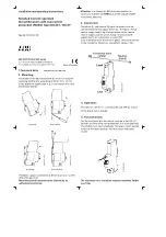
8. Place breaker
fully extended
rails. Make
four rollers
inside grooves (Outside
grooves fit into stationary rails inside cell). (Figure 7).
Figure 7
9. Draw-out mechanism on breaker should be in
position.
10. Push breaker inside the cell until racking-i” cranks
engage a positive stop. This is the OUT position.
11. Close and fasten the door. The metal mask provided
on outside of front box
freely back
it
in contact with the door. The door should
all the way with the breaker in the OUT position.
12. Push
interlock to left, insert
lever
1101-9251, (Figure 8) into the bottom hole of the
mechanism and, with
up-stroke, rack
breaker into the
TEST
position.
Remove
lever,
interlock plate should snap into position com-
pletely covering
holes.
13. Install control power fuses, energizing the circuit. The
motor will
the stored energy mechanism. The
closing and tripping control
become energized
in the TEST position.
14. Open
and make sure that grounding contact in
cell is in
with the breaker. Close door and
check breaker
for proper closing and
opening operation.
If breaker operates properly, rack breaker back to OUT
position and leave there until ready to be put into service.