14
EcoVFC SITE SET UP
20. Verify rotary switch on
Eco
VFC is set to
position 4. This will provide approximately 2.2 bar
(32 psi) output from the IST or STP units with VS2
or VS4 suffix, and serves as a good starting point
for
Eco
VFC calibration.
21. Using a 19 liter (5 gallon) capacity minimum
approved container, go to the dispenser closest
to the storage tank and perform a Flow Rate Test.
If the product being pumped is gasoline, consider
following the U.S. EPA Fuel Dispenser Flow Rate
Test Procedure for 38 LPM (10 GPM) maximum
flow rate standard, where applicable.
Note:
It is necessary to perform a Flow Rate Test for each
product available at the dispenser. This will confirm
that all product outputs, including products blended
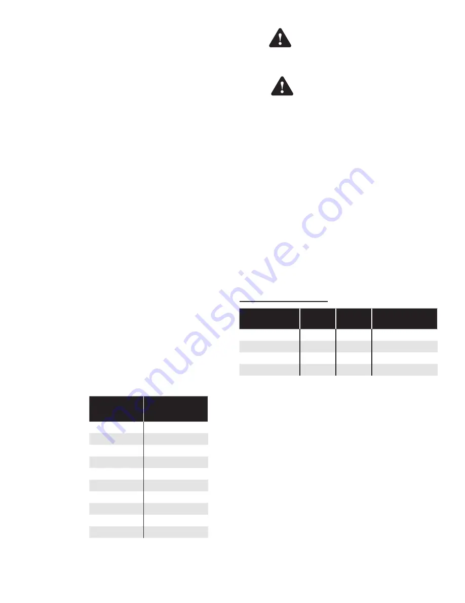
at the dispenser, do not exceed the U.S. EPA 38
LPM (10 GPM) maximum, where applicable.
Note
: Use of “flow restrictors” to control a maximum flow
rate of 38 LPM (10 gpm) per nozzle (as required
by the U.S. EPA) are not required if the variable
frequency controller is properly calibrated as
defined in “
Eco
VFC Site set up Section” section.
22. If output is above or below the desired range (i.e.
30 -38 LPM or 8-10 GPM), turn off the pump at the
power supply, (wait one minute after LED display
blanks before opening the cover) remove the
Eco
VFC cover, and adjust the rotary switch (SW1),
see Figure 2. This switch will increase or decrease
the system operating pressure according to Table
4. An increase in pressure will normally yield an
increase in flow rate; a decrease in pressure will
reduce flow rate. Replace the
Eco
VFC cover and
re-apply input voltage. Return to Step 21 above
and check LPM (GPM) with the new settings.
Repeat until the output obtained is within the
desired range in LPM (GPM).
Switch
Position
Pressure
0
1.7 bar (24 psi)
1
1.8 bar (26 psi)
2
1.9 bar (28 psi)
3
2.1 bar (30 psi)
4
2.2 bar (32 psi)
5
2.3 bar (34 psi)
6
2.5 bar (36 psi)
7
2.8 bar (38 psi)
8
2.9 bar (40 psi)
9
42 psi
Table 4: SW1 Settings
To avoid the risk of potentially lethal
electrical shock, explosion or fire,
always tag and lock circuit breakers
in the off position before removing the
cover of the EcoVFC.
After disconnecting power to the
EcoVFC, wait one minute after LED
display blanks before opening the
cover for servicing. Voltage stored
in the capacitor bank of the EcoVFC
presents a risk of potentially lethal
electrical shock even after power is
disconnected.
Note: Additives in gasoline can change the specific
gravity of gasoline, which may cause the pressures
stated in the above Table 4 to vary.
23. Optimize Pipe Compensation settings by doing
another Flow Rate Test; this time with two other
nozzles from the same product open at the same
time as your test nozzle. If the flow rate at the
test nozzle falls from the desired range with three
nozzles open, increase SW3 pole 4 and pole 5 to
the next highest compensation setting (0 to 1 or
1 to 2 for example). If output exceeds the desired
range, decrease to the next lowest compensation
setting (2 to 1 or 1 to 0 for example). Repeat this
step until compensation setting is optimal for your
installation. Factory setting is zero.
SW3 pole 4 and pole 5
Compensation
SW 3
Pole 4
SW3
Pole 5
Piping
Configuration
0
on
on
least restrictive
1
on
off
...
2
off
on
...
3
off
off
most restrictive
Table 5
Note
: An example of a small restriction piping system
would be 2" fiberglass running less than 45m
(150'). An example of a restrictive piping system
would be 1 ½" convoluted flexible piping greater
than 23m (75') in length.
Note
: When working with a Master-Slave or Master-
Slave/Alternating Circuit configuration, the piping
compensation must be identical in all controllers.
Factory Setting
>
Warning
Warning
Summary of Contents for EcoVFC
Page 26: ...2016FFS 228001102 Rev 10...


