


Page 16 of 91
Rev. 4.20
2.5.8 Connection to the power supply
Execute the connections with suitable materials and procedures prescribed by the rules in force.
Do not execute the electrical connection unless you have verified the actual power cut-off.
PLEASE NOTE
•
At the moment of installation always connect the mains 230Vac first and then the batteries. In this manner
you prevent dangerous shock sparks.
•
The power cable for the Control Panel must be connected, for safety reasons and to facilitate
maintenance, to a magneto thermic switch dedicated and with proper electrical specifications. The
electrical connection should be direct without any kind of by-pass plug or prongs.
•
The minimum required size of cable for power supply must be of 1,5mm² e 250Vca.
•
The ground wire (yellow/green) and properly connected by the ground fastner screw from the power
supply to the other end of the mains power. Furthermore, it must be properly fixed with the screws
provided so to ensure it from mechanical solicitations.
•
All cables connected to the Control Panel must be fire proof.
•
Since the connection to the mains is not off the ground so it does not require any further fastening or
special support to the Control Panel. Shall the case require, please carefully apply any extra cable
connection between the Control Panel and the magneto thermic switch so that the cables and the end
terminals will not be subject to pulls or jerks in their passage way.
•
To apply the connector cable to the power supply. the conductor cable endings should be "pin type", this
to ensure and maintain the safety conditions.
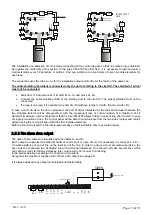
2.5.9 Battery connections
On the control panel electronic circuit board there is a fitting to host the power supply from the two auxiliary
batteries.
In the actual connections, pay careful attention to the polarities and to the color differentiation of the cables and
battery terminals. In case of faulty connection, the circuit breaker fuse which is removable will protect the battery
and circuit board.
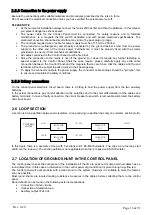
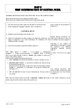
2.6 LOOP SECTION
A section is a loop partition between two isolators. A loop carrying no partition has only one isolator, section (A-B).
In this figure there is a example of loop with 5 sections and 4 EX-MEIS isolators. The clips A are the loop start
and B are the loop end. The section partition is not applicable when there’re passive EX-ISO isolator.
2.7 LOCATION OF GROUND SHUNT IN THE CONTROL PANEL
The control panel checks the connection of the installation all the time to point out if some external cables have a
round dispersion. In this case an information in the control panel of ground shunt is given through a yellow led.
The control panel will work properly with a round shunt in the system. However it is suitable to solve the fault as
soon as possible.
Most round shunts are located making resistance measures in the cables before collecting them to the control
panel.
Round shunts can be found in the following external connections:
•
Connection of siren circuits.
•
Connection of detection loop.
•
Auxiliary output of 24 Vdc.
ISOLATOR
121
ISOLATOR
122
ISOLATOR
123
ISOLATOR
124
CONTROL
PANEL
A-121
121-122
122-123
123-124
124-B