uEZGUI-EXP-DK
User’s Manual
Copyright ©2013, Future Designs, Inc., All Rights Reserved
Page 1: ...uEZGUI EXP DK User s Manual Copyright 2013 Future Designs Inc All Rights Reserved...
Page 2: ...____________________ 9 19 Potentiometer VRES_____________________________________________________________________ 10 20 FET Driver J10 _________________________________________________________________...
Page 3: ...O Expansion Ability to disconnect unused features 4 Requirements The uEZGUI EXP DK comes with the necessary flex cables to begin development right away with the purchase of a compatible uEZGUI kit A 7...
Page 4: ...I 1788 43WQR with uEZGUI EXP DK revision 1 is shown in this picture After connecting the cables connect a 7V 24V DC power supply minimum of 1A to the 2 1mm barrel plug P8 on the EXP DK to power on the...
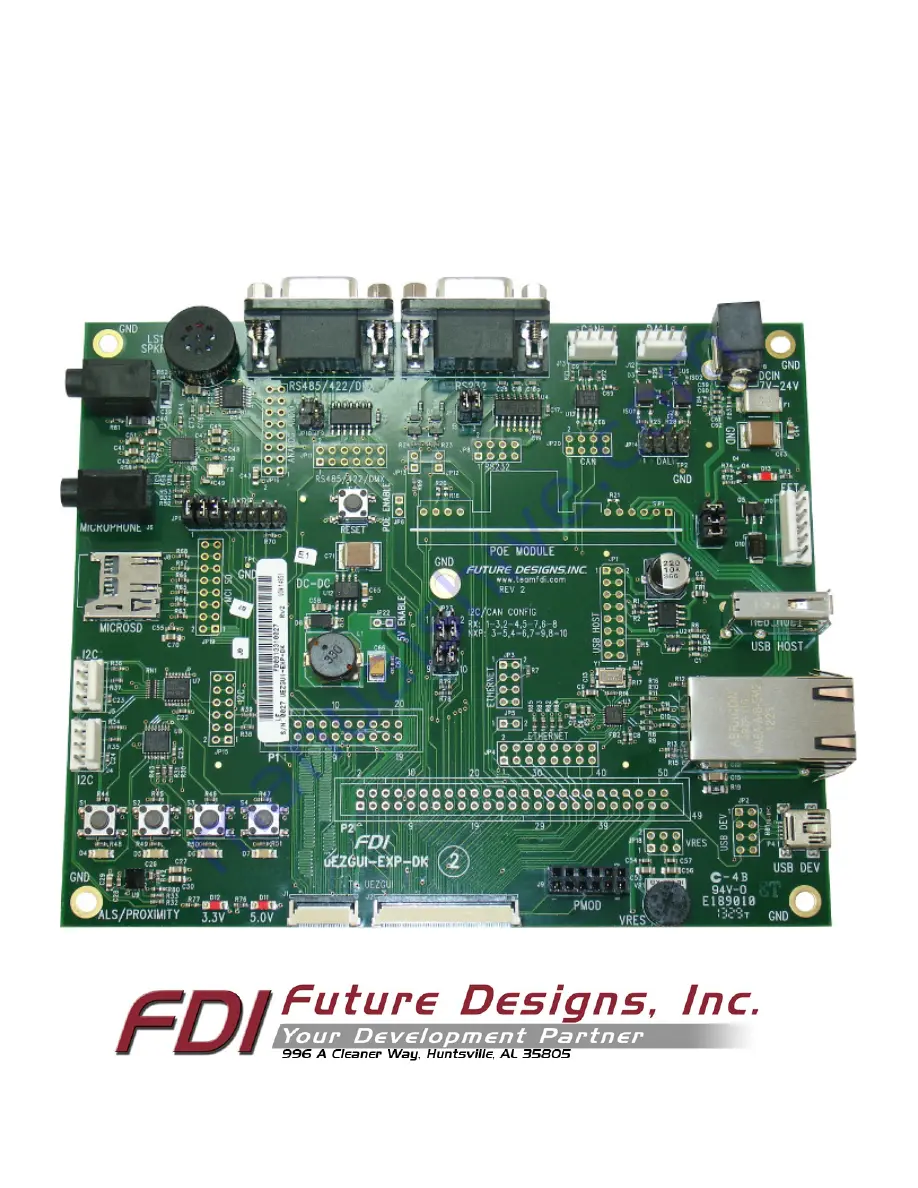
Page 5: ...3 8 Expansion Board Top Level Mechanical Diagram Board Layout Below is the top level mechanical drawing of the uEZGUI EXP DK Rev 2 showing all of the part positions and silkscreen...
Page 6: ...4 9 Expansion Board Functional Block Diagram The uEZGUI EXP DK includes the following features on the specified expansion pins...
Page 7: ...on EXP DK 1 Ground GND Ground 2 USBID GPIO input to uEZGUI to detect a USB OTG host adapter cable on P41 3 Unused Expansion pin not used by EXP DK 4 DALITXD DALI transmit output from uEZGUI host unit...
Page 8: ...Sensor 22 Ground GND Ground 23 RESETIN Reset switch and ISP reset input into host uEZGUI micro controller 24 RESETOUT Reset output from micro controller to Ethernet PMOD I2C Mux and I2C 25 AOUT DAC Ou...
Page 9: ...WM14317 ND Note These lengths are only recommendations The actual lengths utilized will be dependent on the expansion board circuitry layouts and general environment of the application It is up to the...
Page 10: ...ZGUI 1788 43WQR Note The USB Device connector of the Expansion Board is connected in parallel to the USB Device connector of the uEZGUI Main board To avoid damage or improper operation do not connect...
Page 11: ...c R18 and R20 can be loaded to adjust the 12V output See the AG9120 S datasheet for details Note that most uEZGUIs average around 1W 3W power draw so class 1 or class 2 would be suitable for most uEZG...
Page 12: ...ver to be enabled J10 Pin Number Description 1 Ground FET Source gate 2 Ground FET Source gate 3 FET Drain gate 4 FET Drain gate 5 FET Drain gate through diode D10 6 FET Drain gate through diode D10 2...
Page 13: ...13 must be loaded Note that with these jumpers loaded operation of the LPC1788 may be affected by the RS232 interface signals Refer to the FlashMagic user manual for details The ISP programming mode o...
Page 14: ...nto JP9 and JP10 for half duplex mode P6 Pin Number Description 1 No Connect 2 485_RDB 3 485_TDA 4 Signal Ground 5 Signal Ground 6 No Connect 7 485_RDA 8 485_TDB 9 No Connect 25 CAN J13 The UEZGUI EXP...
Page 15: ...Proximity sensor shown below The I2C C and D busses are connected to the two expansion ports J4 and J5 Each expansion port has the following pinout JP15 Pin Number Description 1 2 3 3V 3 4 I2C SDA 5...
Page 16: ...6 3 4 DAC from C to I2S Codec JP16 5 6 DAC from C to I2C Amp JP16 7 8 I2S Codec to I2C Amp JP16 9 10 I2C SCL to I2C Amp JP16 11 12 I2C SDA to I2C Amp JP16 13 14 3 3V to I2C Amp JP16 15 16 Ground to I2...